
StepMCore UDP
The StepMCore UDP is used to create stator and rotor cores for Variable Reluctance (VR), or Hybrid, stepper motors, as shown as in the first figure for a stepper motor and in the second figure for the stator and rotor.

Hybrid Stepper Motor

Stator and rotor of a stepper motor
Parameter Definitions
| Property | Description |
|---|---|
| DiaGap | Core diameter on gap side, DiaGap < DiaYoke for outer cores |
| DiaYoke | Core diameter on yoke side, DiaYoke < DiaGap for inner cores |
| Length | Core Length |
| Poles | Number of poles |
| PoleType | Pole type: 0, 1, or 2 (not valid for inner cores) |
| EmbraceShoe | Pole shoe embrace related to pole pitch for WidthShoe computation |
| HeightShoe | Pole shoe height at pole center |
| WidthBody | Pole body width |
| HeightBody | Pole body height |
| Bp1/Rp1 | Bp1 for pole type 1; or Rp1 for pole type 2; not valid for type 0 |
| Bp2/Rp2 | Bp2 for pole type 1; or Rp2 for pole type 2; not valid for type 0 |
| SurfaceTeeth | Number of surface teeth per pole (>=1) |
| IndexingTeeth | Number of indexing teeth for tooth pitch computation, not valid for SurfaceTeeth=1 |
| EmbraceTooth | Tooth embrace related to tooth pitch, not valid for SurfaceTeeth=1 |
| HeightTooth | Surface tooth height, or slot depth, not valid for SurfaceTeeth=1 |
| FilletSlot | Fillet radius at slot bottom |
| GapCore | Gap of two core sections in radial direction (>0 for Hybrid core) |
| ThickYoke | Thickness of solid yoke in radial direction for Hybrid core |
| ThickMag | Magnet thickness in radial direction for Hybrid core |
| LengthMag | Magnet length in axial direction for Hybrid core (>=GapCore) |
| CoilEndExt | One-side coil end extended Length |
| LenRegion | Region length |
| InfoCore | 0: core; 1: core & coils; 2: coil; 3: magnet; 4: terminal1; 5: terminal2; 6: poles; 7: yoke; 100: region |
Main parameters described in the table above for different pole types are shown in the figures below.
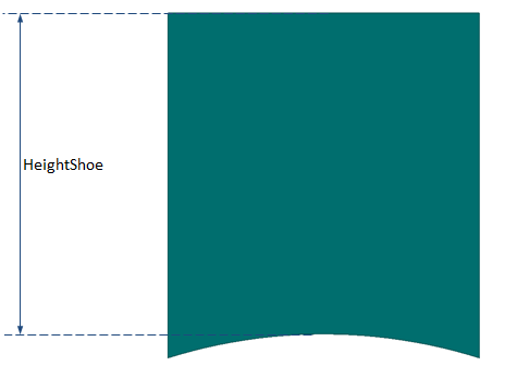
Pole parameters for PoleType = 0
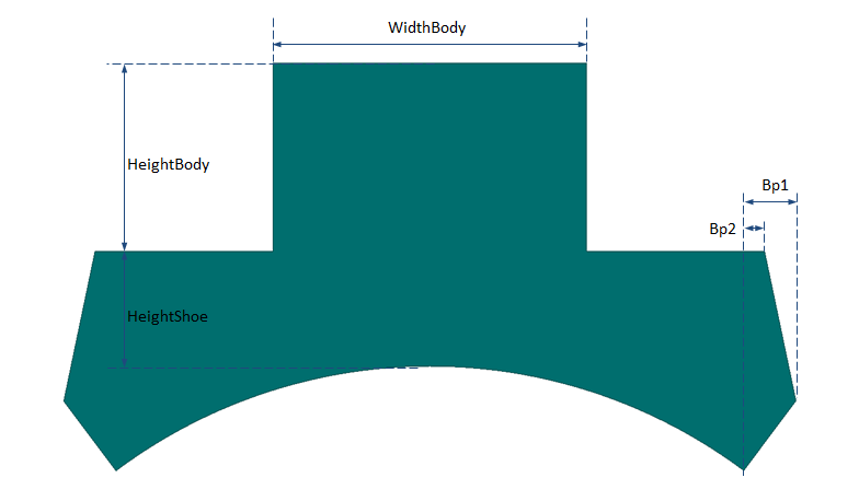
Pole parameters for PoleType = 1
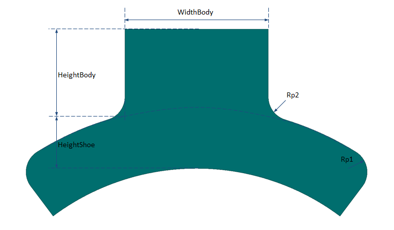
Pole parameters for PoleType = 2
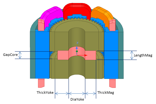
Pole parameters for hybrid rotor
EmbraceShoe is the ratio of the pole shoe angle to pole pitch, and EmbraceTooth defines the ratio of a tooth angle to tooth pitch is: ToothPitch = 360°/IndexingTeeth.
When SurfaceTeeth = 1, which means there are no slots on the shoe surface, the shoe width, noted as WidthShoe, will be directly obtained from EmbraceShoe. When SurfaceTeeth > 1, the minimum shoe angle AngShoeMin will be obtained from the minimum angle to be able to create the specified number of surface teeth, that is
AngShoeMin = (SurfaceTeeth – 1 + EmbraceTooth) x ToothPitch
and the maximum shoe angle is defined to add a half slot in each shoe side, that is
AngShoeMax = AngShoeMin + (1 – EmbraceTooth) x ToothPitch = SurfaceTeeth x ToothPitch.
When the shoe angle corresponding to the specified EmbraceShoe is out of the range of (AngShoeMin, AngShoeMax), the UDP will automatically adjust the value of EmbraceShoe, as shown below.
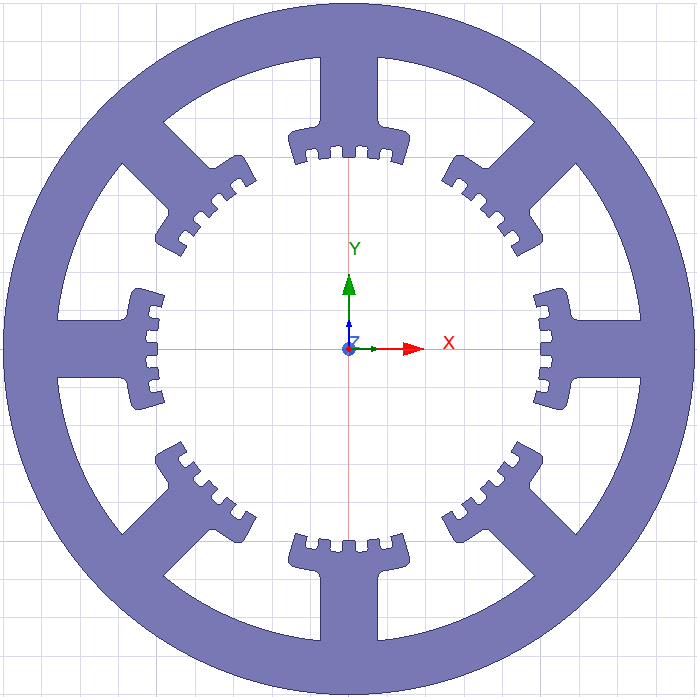
EmbraceShoe = 0.7 (Automatically adjust to 0.72) |
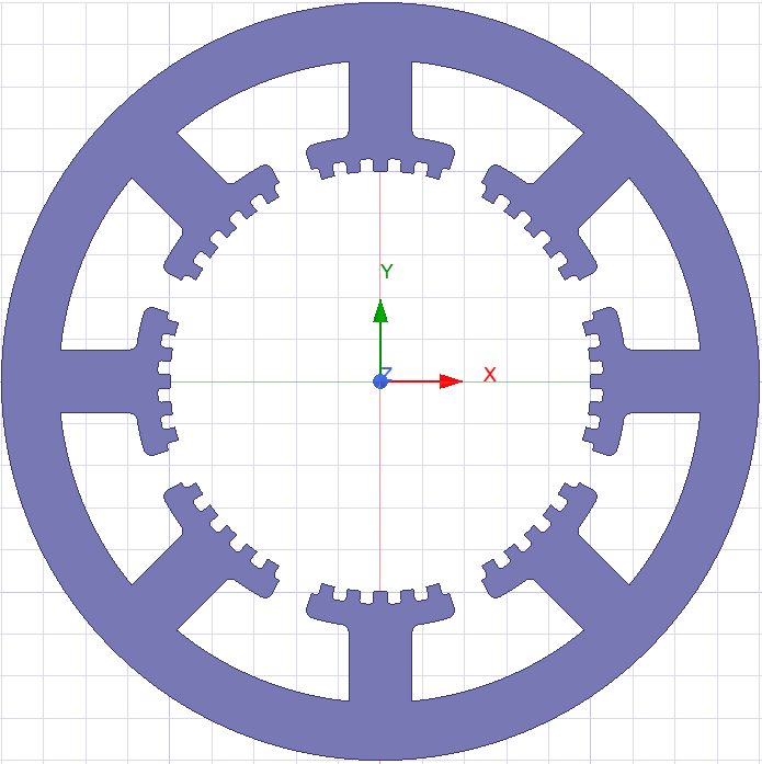
EmbraceShoe = 0.9 (Automatically adjust to 0.8) |
In this example, an 8-pole stepper motor stator has SurfaceTeeth = 5, IndexingTeeth = 50 and EmbraceTooth = 0.5. Therefore, ToothPitch = 7.2°, and AngShoeMin and AngShoeMax will be 32.4° and 36°, corresponding to minimum and maximum shoe embrace of 0.72 and 0.8, respectively. The value of EmbraceShoe will automatically be adjusted to 0.72, or 0.8, if the input value is out of the range.