
Steady-State Conditions
The DC conduction solver assumes that current flow in the conducting material has already reached steady state conditions. The implication of this assumption becomes clear when you compare the initial and steady state conditions of a simple problem such as that shown here:
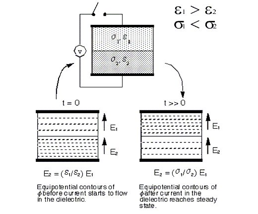
First, consider the interval before steady state is reached. Assume that the switch establishing the potential across the parallel plates in the figure above closes at t = 0. Also assume that the current required to deposit charges on the parallel plates (so that the voltage difference can be supported) occurs instantaneously.
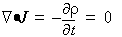
However, it will take a while for current to start flowing in the dielectric. The time it takes for current to flow is determined by the time constant of the material. Therefore, at t = 0, there will be an electric field in the dielectric, but no current and no free charges. Consequently, the relationship that must be satisfied at the interface of the two dielectrics is Ñ·D = r or, equivalently, Ñ·eE = r.
At the interface between the two dielectrics, this relationship implies that

where En is the normal component of E. Therefore, at t = 0, before current starts to flow in the two dielectrics, F(x,y) is determined entirely by the permittivity of the dielectrics. Use the electrostatic field solver to solve for F(x,y) in such a case.
After current starts to flow in the dielectric and steady state is reached, free charges are able to accumulate at the boundaries of the two dielectrics. The free charge, r, is no longer zero.
The relationship that must be satisfied now is
or, equivalently, Ñ·sE = 0.
This relationship implies that

In this case, the solution depends on the conductivity (s) of the materials rather than on their dielectric constant (e). The DC conduction solver analyzes the steady state condition. Therefore, use the DC conduction field solver when steady state conditions have been reached.