
Sinusoidal Current Source
This is an independent current source with an exponentially damped sinusoidal waveform of the current as a function of time. The arrow symbol shows the direction of the positive current flow through the current source.
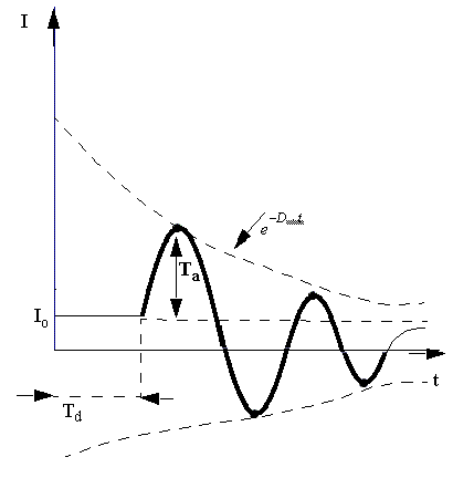

The equation describing the waveform is

where
- I0 is offset current in Amps.
- Ia is the peak amplitude in Amps.
- IFreq is the signal frequency if type is TIME.
- Td is the delay time in seconds if type is TIME.
- Phase is the signal phase delay if type is TIME.
- Df is the damping factor in 1/seconds if type is TIME.
If the type is POSITION, the frequency should be calculated based on the respective spatial periodicity, taking into account the fact that t in the above equation is measured in degrees for rotational type of motion and in the user-defined geometry units for translational type of motion. The delay and damping factor should also be interpreted accordingly.
If the type is SPEED, the frequency should be calculated based on the respective speed periodicity, taking into account the fact that t in the above equation is measured in rpm for rotational type of motion and in the user-defined geometry units per second for translational type of motion. The delay and damping factor should also be interpreted accordingly.
Additional Considerations
To simplify the coupling equations for the field solver, Ansys uses loop analysis method in the circuit solver. That is, the circuit solver will forward a loop matrix and a loop voltage vector to the field solver, and the field solver will return solved loop currents to the circuit solver. When one or more windings are excited by ideal current sources in an external circuit, the loop matrix forwarded to the field solver will be singular. In such a case, the coupling algorithm is changed to directly forward current values from the circuit solver to the field solver. This will cause large errors when some windings are excited by current sources while some windings are excited by voltage sources because the currents of all voltage-excited windings are estimated based on the parameters of the previous timestep.
To avoid errors in current estimation, the solver transforms all ideal current sources to real current sources with a large internal parallel resistance by connecting a large parallel resistance. The reasonable value of such large resistance is 1e08 ohm. If the value is too large, all normal component resistance in the same loop with this large resistance will be "eaten" by the resistance which makes the loop matrix singular. If it is too small, the bypass current through the large resistance will cause inaccurate current through a component connected in series with the current source. Like a real voltage source with a small internal series resistance in which the terminal voltage will change with the load resistance, the load current of a real current source with a large internal parallel resistance will change with the load resistance.
The error between the load current and the source current depends on load resistance. Since the parallel resistance of the current source is internally fixed as 1e08 ohm, the error will be within one percent if the load resistance is limited with 1e06 ohm. This limit is due to the transformation of current source, instead of the switch.