
Setting Up an External Circuit Connection for an External Winding Type
The Maxwell Circuit design editor is used to set up the external circuit excitation for windings in Maxwell 2D and 3D transient solutions.
To set up an external circuit connection for an External winding type:
-
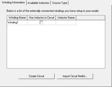
Click Maxwell 3D > Excitations > External Circuit > Edit External Circuit to open the Edit External Circuit dialog box. You can also right-click on Excitations in the Project tree and select External Circuit > Edit External Circuit.
- If no external winding connections have been set up for your model, the Winding Information tab lists the external winding(s) in the design. Continue with step 2.
- If external windings have already been set up, continue with step 7.
-
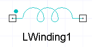
On the Winding Information tab, click Create Circuit to add a circuit design to the project. The new circuit design automatically opens for editing in the Maxwell Circuit Editor. The circuit includes one inductor for each external winding in the original Maxwell transient design. The following example is for a design having one external winding.
-
Add the components needed to complete the external circuit design such as shown the following example.
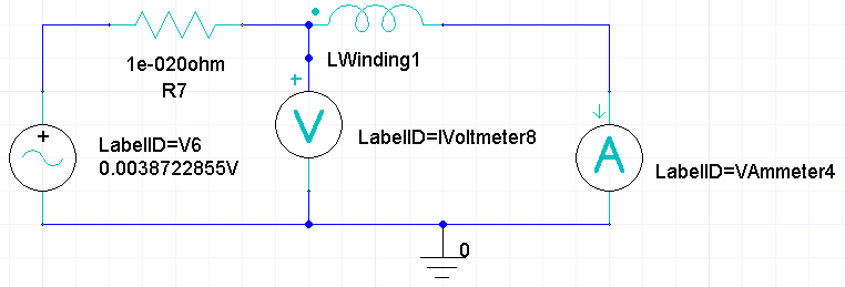
- When the circuit design is finished, click Maxwell Circuit > Export Netlist and export the netlist .sph file to the desired location.
- Return to the Maxwell design and click Maxwell 3D > Excitations > External Circuit > Edit External Circuit to open the Edit External Circuit dialog box. You can also right-click on Excitations in the Project Manager tree and select External Circuit > Edit External Circuit.
- On the Winding Information tab, click Import Circuit to import the circuit.
- To view a list of inductors in the imported circuit, click the Available Inductors tab.
- To view the sources used in the externally connected windings, click the Source Type tab.
- If variables are used in the imported circuit, they and their design values are listed on the Parameter Values tab. You can link to variables within the imported circuit as follows:
- On the Parameter Values tab, click in the Value column of the parameter to be mapped.
- Enter a new local variable name and press the Enter key to open the Add Variable dialog.
- Select a Unit Type and Unit, and enter a Value for the variable and click OK. The new Maxwell variable is now mapped to the variable in the imported circuit, and can be varied directly by Maxwell or used for optimetrics analyses.
- If the imported file is a .sph file, you can click the Circuit Path tab to view the original project and design names (which are removed after you import a non-sph file).
- Click OK to close the Edit External Circuit dialog box.
For transient designs, the user-set timesteps can be modified when external circuits are used to drive the windings of a transient finite element model. Following is a list of situations that will lead to a timestep change:
- All power electronic switching instances that do not coincide with user-specified solve times request a new solution time from the transient solver. The respective switching generating a new solve time request for the transient solver can be time, position, or speed dependent.
- When current and/or voltage sources with a piecewise linear variation are used, a new solution time is requested from the transient solver at each (time) definition point used in the corresponding source definition table.
- When the change in any winding inductance value is excessive, a new timestep (smaller) is calculated and a new solution generated (recalculated) accordingly.
If a user-specified save field time is missed because of the above reasons, the next solved timestep fields are saved instead.
Related Topics
Assigning a Winding Setup for a Transient Solver