
Rounding the Edge of an Object (Fillet Command)
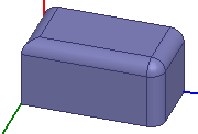
The fillet command rounds the object at the original edges and vertices. This means that the edges and vertices are going to be replaced by new rounded surfaces, so that the original faces of the object reconnect in a smooth manner.
Vertices are only going to be replaced by new rounded surfaces if all the edges connecting to the original vertex are selected; otherwise, the vertex is preserved but moved (if necessary). The edges are replaced by quarter-cylindrical surfaces, of which the radius can be customized (see the Fillet Radius property). Vertices are replaced by more complicated new faces. You can control the setback distance.
The fillet command is disabled if an edge is not selected.
To switch to edge selection mode:
- Right-click the desktop, and select Selection Mode > Edges from the shortcut menu.
To round an object's edge:
- Select the edge you want to change.
- Click Modeler > Fillet, or click the Fillet icon on the Draw ribbon.
- Enter a value for the Fillet Radius in the text field and select units from the drop down menu. The default is millimeters.
- Enter a value for the Setback distance.
- Click OK to apply the change to the edge.
The edge is highlighted, and the Fillet command is enabled.
The Fillet Properties dialog box appears.
The setback distance controls the shape of the vertex. It is the distance of the cross curve from the vertex at the end of the edge. If it is less than the fillet radius it has no effect. You will get an error if it is greater than the length of the edge.
The dialog closes and the object is rounded by the radius value relative to the edge you selected.