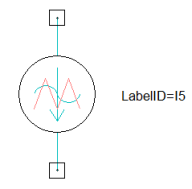
PWM Current Source
The PWM current source component shown below provides PWM control signals used to support TDM parallel computation. (Refer to Time Decomposition Method for Maxwell Transient Designs in the Maxwell help.) The arrow symbol shows the direction of positive current flow through the current source.
Because all timesteps in one subdivision along the time axis are solved together when TDM is used, all controlling signals in a control circuit cannot depend on solutions such as currents/voltages of the previous timestep. Therefore, all diodes and switches which are controlled by independent voltages and currents are not supported.
In PWM control, the controlling signals are purely time and/or position dependent, therefore, PWM control is supported in TDM. In a PWM control circuit, since the upper and lower switches belong to the same phase are turned on and off at exactly same time, the free-wheeling diodes are not necessary. In order for users to directly use existing PWM control circuit, PWM current and voltage source components have been introduced to replace original controlling sub-circuit which includes a triangle current/voltage source connected in series with a sinusoidal current/voltage source. The circuit solver will detect all switches which are controlled by PWM current/voltage sources and automatically filter all related diodes, which means during the simulation, diodes are automatically excluded in PWM control circuit.
An IPWM current source is defined by the following parameters:
-
ModuIndex is the modulation index, the ratio of control-signal amplitude to carrier-signal amplitude.
- FreqTime is the ratio of carrier-signal frequency to control-signal frequency.
- IFreq is the frequency of the control signal, if Type is TIME.
- Phase is the phase delay of the control signal, in electrical degrees.
- Type can be chosen as either TIME or POS, defining the output signal as a function of time or position.
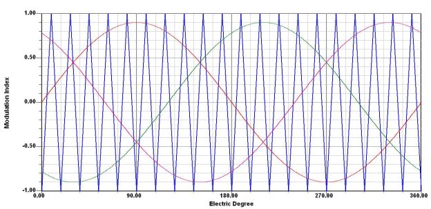
The following figure shows typical three-phase PWM control signals: