
Inductance in Terms of Flux Linkage and Currents
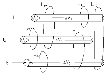
An inductance matrix represents the magnetic flux linkage between the current loops in a system. Given the three current loops below, the relationship between induced flux and currents is as follows:
l1 = L11 i1 + L12 i2 + L13 i3
l2 = L12 i1 + L22 i2 + L23 i3
l3 = L13 i1 + L23 i2 + L33 i3
This can be expressed in matrix form as

The inductance matrix above gives the relationship between l and i for the three independent current loops. In a device with n current loops, this relationship would be expressed by an n´n inductance matrix. Inductance matrix values are specified in henries.
If one ampere is applied to Current Loop 1 and zero amperes are applied to the other two loops, the inductance matrix becomes

The diagonal terms in the matrix (such as L11) represent the self-inductance of each current loop. Self-inductance is numerically equal to the flux linkage in a current loop when one ampere is flowing in it, and no current is flowing in the other loops. For example, L11 is equal to the flux in Current Loop 1 when one ampere is flowing in that current loop, and no current is flowing in the other loops.
The off-diagonal terms (such as L12, L13) represent the mutual inductances between the current loops. Mutual inductance is numerically equal to the flux linkage in a current loop when one ampere is flowing through another loop, and no current is flowing anywhere else. For example, L12 is equal to the flux linkage in Loop1 when one ampere is applied to Loop 2 and no current is flowing in the other loops.
Note that the inductance matrix is symmetric about the diagonal. This indicates that the mutual effects between any two loops are identical. For instance, L13, the inductance between Current Loop 1 and Current Loop 3, is equal to the inductance between Current Loop 3 and Current Loop 1.