
Inductance and Resistance in Impedance Computations
The inductances and resistances computed during an impedance matrix solution are different from those computed for the equivalent DC case. This figure shows how they differ:
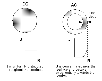
The current density, J, in the DC case (the conductor on the left) is evenly distributed throughout the cross-section of the conductor. The current density in the AC case (the conductor on the right) is distributed nonuniformly on the surface due to skin effect. Because the area through which current can flow is smaller, it follows that the resistance to the current flow is higher in the impedance matrix than in a resistance matrix computed for the equivalent DC case.
In the DC example, no eddy currents occur. The magnetic field created by the current flowing through the conductor is static. In the AC example, the oscillating magnetic field induces currents in conductors in the model. These induced currents affect the computation of inductance for the impedance matrix, causing it to be different from the equivalent DC computation of inductance.