
Independent/Dependent
Independent/Dependent boundaries are available for use in Magnetostatic, Eddy Current, Transient, Electrostatic, AC Conduction, and DC Conduction solver type designs. Matching boundaries allow you to take advantage of periodicity in a structure. For example, the following figure shows the cross-section of a DC motor. The field in such a motor repeats itself every 120 degrees; that is, the field pattern in one third of the motor matches the magnitude and direction (or the opposite of the direction) of the field pattern in the other two thirds.
Matching boundaries force the magnetic field at each point on one boundary (the “dependent” boundary) to match the magnetic field at each corresponding point on the other surface (the “independent” boundary). Modeling one third of the structure allows you to make efficient use of the available computing resources:
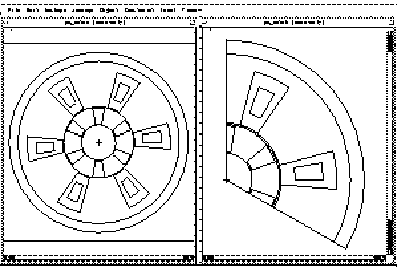
To define matching boundaries, you must define both an independent matching boundary and a dependent matching boundary.
The condition that needs to be enforced, as illustrated in the following figure, is that the magnitude of the magnetic field at each point on the dependent boundary surface must match the magnetic field at each corresponding point on the independent boundary surface. The field on the dependent boundary must point in either the same direction or in the exact opposite direction as the field on the independent boundary:
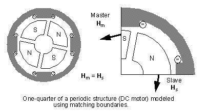
Note that a Vector Potential (Dirichlet), Neumann or symmetry boundary cannot be used to simulate periodicity because the magnetic field is not necessarily either perpendicular or tangential to periodic surfaces. For example, in the quarter model shown above, the magnetic field is exactly perpendicular to the bounding surfaces only when the gap separating the permanent magnets is perfectly horizontal or vertical. For all other positions of the rotor, matching boundaries are required to take advantage of symmetry.