
Impedance
The impedance boundary is available for use in Eddy Current solutions. Impedance boundaries allow you to simulate the effect of induced currents in a conductor without explicitly computing them. The ohmic loss due to induced currents is computed from the tangential components of the H-field along the impedance boundary — the surface of the object that you are interested in.
Use this boundary condition for models where the following conditions occur:
- The skin depth in the conductor of interest is less than two orders of magnitude smaller than the dimensions of the structure. In models like this, the Maxwell 2D’s mesher may not be able to create a fine enough mesh in the conductor to compute eddy currents.
- The magnetic field decays much more rapidly inside the conductor in the direction that is normal to the surface than it does in directions that are tangential to the surface.
- The AC current source is relatively far away from the surface where eddy currents occur, compared to the size of the skin depth.
The object itself must be excluded from the solution region by making the object a perfect conductor. When drawing the geometry, make the surface along which eddy currents are to be computed an outer surface of the problem region. Then, when defining boundaries, assign an impedance boundary to this surface. By entering the conductivity, s, and the relative permeability, mr, of the object, you specify the skin depth of induced eddy currents. The simulator uses this skin depth when computing the electromagnetic field solution. It assumes that the H-field falls off exponentially inside the conductor.
For instance, suppose you want to compute eddy current losses in the conductor next to the current source shown below.
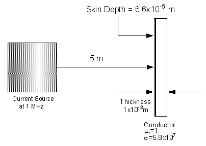
If AC current is passing through the current source at a frequency of 1 MHz, the skin depth in the conductor is given by the following relationship:

where
- w = 2pf = 2p x 106 = 6.28 x 10⁶ radians/second
- s = 5.8 x 10⁷ siemens/meter
- mr = 1
- m0 = 4p x 10-7 henries/meter
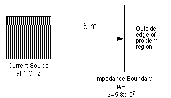
Substituting these values into this equation, the skin depth is found to be 6.6x10⁻⁵ meters. Because this is much smaller than the thickness of the conductor and the surface where currents are induced is relatively far away from the current source, an impedance boundary can be used to model the induced currents in the conductor, as shown below. The conductor itself is not included in the model; instead, the outside boundary of the model is moved to the inside surface of the conductor. This outside surface is defined as an impedance boundary, using the conductivity and permeability specified previously.
After generating a solution, you can compute the ohmic loss for the surface using the plane calculator and plot the loss density on the boundary.
For impedance boundaries, ohmic loss is given by

where
- w is the angular frequency, which is equal to 2pf.
- s is the conductor’s conductivity in siemens/meter.
- mr is the conductor’s relative permeability.
- m0 is the permeability of free space, which is equal to 4p x 10–7 H/m.
- Ht is the tangential component of H on the impedance boundary.
- Ht* is the complex conjugate tangential component of H on the impedance boundary.