
Geometric Objects — Bondwires
A bondwire is a thin metal wire that connects a metal signal trace with a chip. You can choose to draw a standard JEDEC four-point bondwire, as shown below:
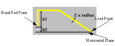
where
h1 = the height between the bond pad point and the top of the loop.
h2 = the height between the lead point and the bond pad point.
radius = half the diameter, or thickness of the wire.
You can draw a standard JEDEC five-point bondwire, as shown below:
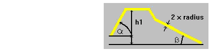
where
a = the angle between the horizontal plane and the wire at the bond pad point.
b = the angle between the horizontal plane and the wire at the lead point.
When drawing the bondwire, first select the bond pad point, a point in 3D space that defines the bond pad position in a horizontal plane. Then select the lead point, which indicates the distance the wire covers in the horizontal plane. Maxwell uses the distance between the bond pad and lead points to calculate the height between the bond pad and the lead point, or h2, a value that you can modify in the Bondwires dialog box.