Excitation Setup
Windings
-
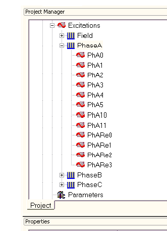
Click on Maxwell2DDesign1 > Excitations > PhaseA in the Project Manager window, all objects assigned to this phase are highlighted in the modeler window.
-
In the Properties window, review all winding properties: Voltage for Winding Type; Stranded for IsSolid; 0.00226117 ohms for Resistance; 8.87325e-005 H for Inductance; 1 for Number of Parallel Branches; 11267.7 * sin(2*pi*50*time-43.4944*pi/180) for Voltage, where 50 is the frequency in Hz, 11267.7 is the phase peak voltage in Volts, pi is a predefined constant, and time is a predefined variable for time. By using sin function instead of cos function, the applied voltage and back EMF are in phase. Therefore, a phase shift in the applied voltage source will be the power angle of the motor. 43.4944 degrees is the power angle at full load operation. The values for resistance, inductance and number of parallel branches are obtained from the TRANSIENT FEA INPUT DATA section in RMxprt design sheet.
-
Click on PhaseB, PhaseC, or Field to review all objects assigned to this winding in the modeler window, and winding properties in the Properties window.
Coil Terminals
A winding consists of several coil terminals, and two coil terminals represent a coil in a complete 2D model. Because we are working with only one-half of the motor structure, one coil terminal can represent one complete coil with independent/dependent boundary conditions provided.
A coil terminal has properties of Number of Conductors and Polarity Type. Number of Conductors is the number of turns per coil, and it is equal to the Number of Turns given in RMxprt divided by number of coils per phase. Polarity Type defines the direction of the current in the coil; it can be either positive or negative.
-
Expand a winding and click on a coil terminal to review the object corresponding to this coil terminal in the modeler window and all coil terminal properties in the Properties window. In this example, Number of Conductors of A, B, and C coil terminals is assigned as 1, and it is 12 for the Field windings.
-
Click on PhaseB, PhaseC, or Field to review all objects assigned to this winding in the modeler window, and winding properties in the properties window.
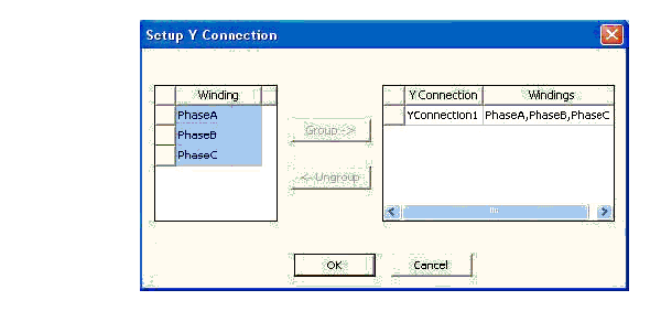
Y Connection for Three-Phase Windings:
- Right-click on Maxwell2DDesign1 > Excitations in the Project Manager Window, and click Setup Y Connection… in the pop-up panel.
- Review the Y -connection setup.