
ECESRM Model
The ECESRM model enables you to create an ECE model of a switched reluctance motor from Maxwell 2D and 3D Transient solutions.
To change the name of the model placed on the sheet, click the symbol on the sheet, and change the name of the component in the property window (Value field in the DeviceName line, with the Parameter Values tab selected).
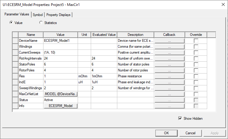
The ECESRM_Model contains the following parameters:
- DeviceName – the name of the device model with default name ECESRM_Model1.
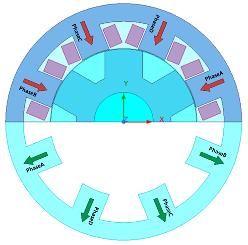
- Windings – specifies winding names in the order of arrangement. Windings are separated by commas or semicolons. If two adjacent windings are defined with the same polarity, they will be separated by a comma “,”, otherwise by a semicolon “;”. For example, for an 8/6 pole SRM, as shown below, windings for phase A, B, C and D are arranged in clockwise direction. The adjacent two windings of phase A and phase B have different polarities, and all other two adjacent windings have the same polarities. Therefore, windings can be specified in ECESRM_Model as:“PhaseA; PhaseB, PhaseC, PhaseD”where the separator between PhaseA and PhaseB is “;”, indicating different polarities between them. The last separator between PhaseD and PhaseA is not required because the total number of semicolons should be an odd number, and the last separator can be automatically determined.
- CurrentSweeps – specifies current sweeps in a winding. The first winding in the winding list is always excited with sweeping current. You just need to list 0 and all positive sweeping currents. All negative currents will be swept, or extended, symmetrically from the positive sweeping currents.
- RotAngIntervals – specifies the number of uniform sweeping intervals for rotor position in one rotor-pole region. For a 6-pole rotor, one rotor-pole region will be 60 mechanical degrees. If RotAngIntervals = 24, the sweeping step for rotor position will be 2.5 mechanical degrees.
- StatorPoles and RotorPoles – specifies the numbers of stator and rotor poles.
- Res and IndE – specifies winding resistance and end-leakage inductance for 2D.
- SweepWindings – specifies the number of windings to be excited. The value of SweepWindings could be 0, 1, or 2. Value 0 is for the case that only one winding current is swept, and all mutual effects of other winding currents are ignored; value 1 is for the case that only one winding current is swept, and the mutual effects on winding flux linkage are considered, but the mutual effects of other windings currents on field saturation and torque are ignored; value 2 is for the case that two winding currents are swept, and all mutual effects are considered.
Look-Up Table Processing
For an SRM, if a winding is triggered after the previously triggered winding has finished the free-wheeling process, there will be no mutual effects between the currently triggered winding and the previously triggered winding. In such a case, only one winding is excited with current at any time. In many cases, in order to increase power capacity, a winding could be triggered when the previous triggered winding is still working. In this situation, two windings could be excited with currents in some time periods. Therefore, we will provide different sweep types for different applications, which is specified by parameter SweepWindings, as described below.
-
SweepWindings = 0
SweepWindings = 0 means only one winding is excited, and all mutual effects between windings are ignored. The first listed winding PhaseA is excited with sweeping currents in the range of [0, Im], and the look-up table for the negative currents is automatically extended based on symmetry conditions. The final circuit model derived from this setting is equivalent to the circuit which is manually created by:
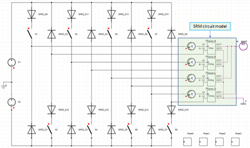
- Obtaining a single-phase circuit sub-model using ECEW_Model and ECER_Model.
- connecting single-phase circuit sub-models for all phases with suitable IniPos settings, as shown in the circuit inside the shaded rectangle below.
This sweep type has the smallest look-up table, which includes controlling variables of one winding current and rotor position, and controlled variables of flux linkage and torque. For this sweep type, it is not necessary to solve the field for negative sweeping currents. The look-up table for the negative currents can be automatically extended based on symmetry conditions, as given below:

where Fthis(Ithis, θ) and T(Ithis, θ), as outputs of look-up table, are the flux linkage of the excited winding and rotor torque, respectively, and the controlling variables Ithis and θ are the winding current and rotor position, respectively.
-
SweepWindings = 1
SweepWindings = 1 means only one winding is excited, and the mutual effects on winding flux linkage are considered, but the mutual effects on field saturation and torque are ignored. In order to easily illustrate windings for look-up table creation, we call the excited winding, PhaseA, as this winding, PhaseB as next winding, and PhaseD as previous winding. In this way, in the first single-phase submodel as shown in the figure above, this/next/previous windings represent phase A/B/D windings. In the second single-phase submodel, they represent phase B/C/A windings, and so on. Only this winding has a circuit inside a single-phase submodel. The mutual effects of the next/previous currents on this-winding flux linkage are considered by

where Fthis(Ithis, θ), Mnext(Ithis, θ), Mpre(Ithis, θ), as outputs of look-up table, are flux linkage, mutual inductance between this and next windings, and mutual inductance between this and previous windings, respectively. Controlling variables Ithis and θ represent this-winding current and rotor position, respectively. The next and previous winding currents, Inextand Ipre, respectively, are delivered via parameters of single-phase submodels. The signs before the next and previous winding currents will be automatically determined in the final SRM model based on the separators for previous, this and next windings. Like the case of SweepWindings = 0, the look-up table for the negative currents can be automatically extended based on symmetry conditions, as given below:

Comparing this with the sweep type of SweepWindings = 0, this sweep type has the same controlling variables with the same sweeping points, but it has a larger-size lookup table because it has more controlled variables.
-
SweepWindings = 2
SweepWindings = 2 means two windings, this and next windings, are excited, therefore all mutual effects on winding flux linkage, field saturation and torque are considered. If CurrentSweep in the ECESRM_Model is specified in the range of [0, Im], the this-winding current will be swept in the range of [-Im, Im], and the next-winding current will be swept in the range of [0, Im]. After field simulations for all sweeps are completed, we obtain a clean look-up table. This look-up table has two controlled variables (this-winding flux linkage Fthis and torque T); and three controlling variables (this-winding current Ithis, next-winding current Inext, and rotor position θ). In this clean look-up table, T is the torque produced by this-winding current but considered the mutual effects of next-winding current. In field analysis, a torque can be derived based on field solutions and be expressed, by numerical integration over all related mesh elements, as

where Bi is the flux-density vector created by all winding currents, and kTi is a coefficient, in mesh element i. If we freeze the permeabilities of all nonlinear materials, the field becomes linear. Then, the flux density vector in any mesh elements can be expressed as:

where B1i and B2i are the flux-density vectors created by this and next winding currents, respectively. Hence, the torque will be

with

In field analysis, we can get T11 by injecting current in this winding only, and we get T22 by infecting current in next winding only. Then we get

Finally, we get torque in the clean look-up table as
 .
.The clean look-up table can be extended to a full look-up table based on even and odd symmetry conditions, as given below:

The flux linkage and torque in the look-up table are derived based on this-winding current with considering the mutual effects of next-winding current. In real operation with two excited windings, we need to get the flux linkage and torque produced by each winding current. For example, in the circuit diagram above, if phases A and B are excited simultaneously, the flux linkage and torque, produced by phase-A current with mutual effects of phase-B current, can be directly obtained from the look-up table because phase-A current is this-winding current and phase-B current is next-winding current, as given below:

where the sign before Inext is positive if the separator between this and next windings is the same as that between the first and second windings listed in the Windings field in the properties dialog box above, or negative otherwise. Because the lookup table includes the mutual-effect information, it is important to transfer the next-winding current to make sure the polarity relationship between this and next windings in a single-phase sub-model is the same as that for lookup table creation. For example, for the phase-A sub-model in the circuit diagram above, this sign is positive because the separator between this and next windings, or between PhaseA and PhaseB, is “;”, which is the same as that between PhaseA and PhaseB for lookup table creation. However, for the phase-B sub-model, the sign is negative because the separator between this and next windings, or between PhaseB and PhaseC, is “,”, which is different from the separator “;” between PhaseA and PhaseB for look-up table creation.
When we consider the flux linkage and torque produced by phase-B current with mutual effects of phase-A current, we cannot obtain them directly from the look-up table because in this situation phase-B current is this-wingding current and phase-A current is pre-winding current, but we can still obtain them from the look-up table based on symmetry conditions. In the winding polarities diagram above, if we mirror the geometry about the center line of the phase-B pole, then phase-A winding aligns with phase-C winding, and rotor position becomes negative. Based on this symmetry condition, we have:

where the sign before Ipre is positive if the separator between this and previous windings is the same as that between the first and second windings listed in the Windings field in the properties dialog box above, or negative otherwise.
In the final SRM model, the signs before Inext and Ipre for all single-phase sub-models will be automatically determined based on all separators listed in the Windings field, which, together with Inext and Ipre, are forwarded to submodels via input parameters.
You can import this ECE model in Twin Builder via the Twin Builder > SubCircuit > Maxwell Component > Add Equivalent Circuit menu command. For more information on coupling Maxwell designs to Twin Builder components, refer to the Maxwell Equivalent Circuit Component topic in the Twin Builder Help.
For more information on coupling Maxwell designs to Twin Builder components, refer to the Coupling Maxwell to a Twin Builder Component topic in the Maxwell Help