
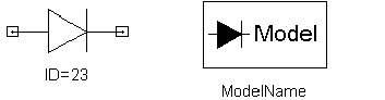
Diode & Diode Model
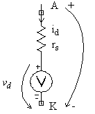
Diode element must always be used together with a diode model. One diode model element can be used as reference for multiple diodes, as needed. Thus, once a diode is placed on the design sheet, a corresponding model must also be present on the sheet. Once both needed elements (diode and diode model) have been placed on the sheet, right mouse click the diode model and specify the parameters as required by the application. Then, right mouse click the diode and create the reference to the corresponding model by entering the name of the model in the MOD line (Parameter Values tab should be selected). If you select the Show Hidden check box, the AREA diode parameter (used below in the model definition) becomes visible. The default value of the AREA parameter is 1.
The diode model used by Maxwell Circuit Editor is a static model as described by the following equation:
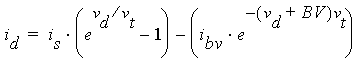
vt = N × (kT)/q
q = 1.6022 × 10⁻¹⁹ C
k = 1.3807 × 10⁻²³(J/K)
T is temperature in K, fixed at 300 K.
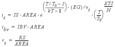
The model parameters are as follows:
- IS is the saturation current in Amps.
- RS is contact resistance in Ohms.
- N is the emission coefficient.
- EG is the barrier height at 0 K, in volts.
- XTI is the diode saturation current temperature coefficient.
- BV is the magnitude of the reverse breakdown voltage in volts.
- IBV is the magnitude of the reverse breakdown current in amps.
- TNOM is the reference temperature in Celsius.