
Defining the Rotor Winding Data for a Three-Phase Synchronous Machine
Use the Rotor Winding window to define the wires and physical dimensions of the rotor winding. The rotor winding provides the excitation for the electromagnetic field that produces the rotor pole.
To define the rotor windings:
- To open the Rotor Winding Properties window, double-click the Machine > Rotor > Winding entry in the Project Manager tree on the desktop. (You can also enter values in the Properties section of the desktop without opening a separate window.)
- Select the Winding Type for the rotor:
- Click the button.
The Winding Type window appears. - Click to select the type of winding,
from Round, Cylinder,
or EdgeWise.
When you place the mouse cursor over the winding type, a schematic of the selected winding appears - Click OK to return to the Properties window.
- Enter the number of parallel branches for the winding in the Parallel Branches field.
- Enter a value for Conductors per Pole.
- If the Round winding type is selected, specify the Number of Strands per conductor. Enter 0 for auto-design.
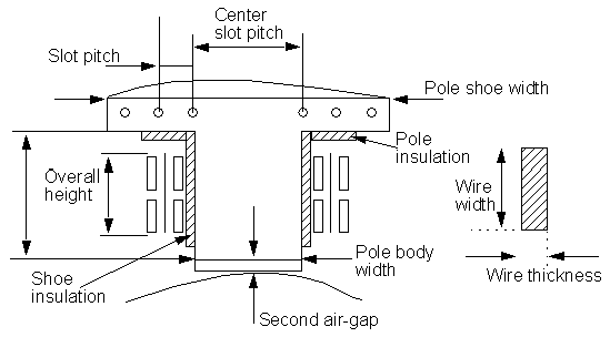
- Enter the width of the insulating wire wrap in the Wire Wrap field.
- For an EdgeWise winding type, enter the thickness of the inter-turn insulation in the Interturn Insulation field.
- Enter the gauge of the wire in the Wire Size field.
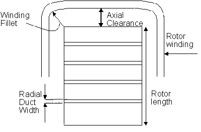
- Enter the Axial
Clearance to specify the axial distance between the core
and the coil at the end of the lamination stack.
-
Enter the limited cross-section width for winding design or arrangement in the Limited Cross Width field. Enter 0 for maximum available area.
-
Enter the limited cross-section height for winding design or arrangement in the Limited Cross Height field. Enter 0 for maximum available area.
-
Enter the inner radius at winding fillet in the Winding Fillet field.
- Click OK to close the Properties window.
Note: The Inter-turn Insulation field is not available when either the Round or Cylinder winding type has been selected.