Defining the Rotor Pole for a Brushless PMDC Motor
The rotor pole drives the electromagnetic field, which is coupled with the stator windings. Use the Rotor Pole Data Properties window to define the rotor pole.
Note: Some of the fields
in the Rotor Pole window change,
or are inactive, depending on the Rotor Type
you select.
To define the rotor pole:
- To open the Rotor Pole Data Properties window, double-click the Machine > Rotor > Pole entry in the project tree on the desktop. (You can also enter values in the Properties section of the desktop without opening a separate window.)
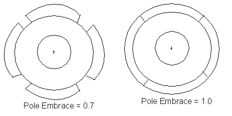
- For all pole types except type 4, enter the ratio of the actual arc distance
in relation to the maximum possible arc distance in the Embrace field. This value is between
0 and 1.

- For pole type 4, enter the shaft diameter of the rotor in the Shaft Diameter field.
- For pole types 1,
2, and 3,
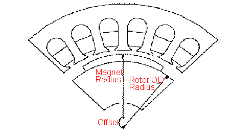
enter the distance from the center of the rotor to the polar arc center
in the Offset field. Enter 0
for a uniform air gap.

- For pole type 5, enter the thickness of the bridge across the two poles in the Bridge field.
- For pole type 5, enter the width of the rib supporting the bridge in the Rib field.
- Select the type of magnet to use in the rotor pole from the Magnet Type drop-down menu.
- For pole types 4 and 5, enter the width of the magnet in the Magnet Width field.
- Enter the maximum radial thickness of the magnet in the Magnet Thickness field.
- Click OK to close the Properties window.
