
Defining the Circuit Data for a Switched Reluctance Motor
Use the Circuit Data Properties window to specify the rated output power, voltage values, circuit type, and speed of the brushless DC motor.
- To open the Circuit Data Properties window, double-click the Machine > Circuit entry in the project tree on the desktop. (You can also enter values in the Properties section of the desktop without opening a separate window.)
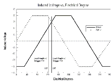
- Enter the trigger’s lead angle in electrical
degrees in the Lead Angle of Trigger
field. The trigger angle is the point at which the magnetic poles interact
to begin the motion of the motor. An angle of 0 means that each phase
is triggered when its axis is aligned with the rotor slot center. The
trigger’s lead angle is shown in the following plot of the open circuit
induced voltage versus position. An angle of 0 means that the induced
voltage in the triggered phase is at a maximum:
 Note: A positive value represents a lead angle, and a negative value represents a lag angle.
 - Enter the period from on-status to off-status of a transistor, in electrical degrees, in the Trigger Pulse Width field. The trigger pulse width is the width of the energizing pulse applied to the winding, or the period for an ‘on’ status of the transistors. The maximum ‘on’ period is given by 180 degrees plus the value for the lead angle of trigger.
- Enter the voltage drop across one transistor when the transistor is turned on in the Transistor Drop field. Refer to the figures of the different circuit types in step 2. This value is over one conduction path when the transistors are triggered.
- Enter the voltage drop on all anti-parallel diodes in the discharge path in the Diode Drop field. If you selected a star-type circuit (S3 or S4) as the Circuit Type, enter the total discharge voltage in this field.
- If you selected CCC (chopped current control) as the Control Type, then enter the maximum and minimum current values in the Maximum Current and Minimum Current fields.
- Click OK to close the Properties window.