
Defining the Circuit Data for a Brushless PMDC Motor
Use the Circuit Data Properties window to define the circuit data for a brushless PMDC Motor.
- To open the Circuit Data Properties window, double-click the Machine > Circuit entry in the project tree on the desktop. (You can also enter values in the Properties section of the desktop without opening a separate window.)
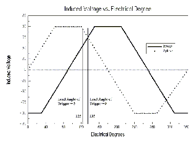
- Enter the trigger’s lead angle in electrical
degrees in the Lead Angle of Trigger
field. The trigger’s lead angle is shown in the following plot of the
open circuit induced voltage versus position. An angle of 0 means that
the induced voltage in the triggered phase is at a maximum:
 Note: A positive value represents a lead angle, and a negative value represents a lag angle.
 - Enter the period from on-status to off-status of a transistor, in electrical degrees, in the Trigger Pulse Width field.
- Enter the voltage drop across one transistor when the transistor is turned on in the Transistor Drop field. Refer to the figures of the different circuit types in step 2.
- Enter the voltage drop of one diode in the discharge loop in the Diode Drop field. If you selected a star-type circuit (S3 or S4) as the Circuit Type, enter the total discharge voltage in this field.
- If you selected CCC (chopped current control) as the Control Type, then enter the maximum and minimum current values in the Maximum Current and Minimum Current fields.
- Click OK to close the Properties window.