DFIG Operating as a Generator
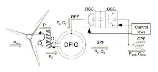
Doubly-fed induction generators (DFIGs) are widely used in wind power systems. A DFIG works as a component of a wind power system, as shown below, where the wind turbine transforms wind energy into mechanical energy, and the DFIG transforms mechanical energy into electrical energy.
For a DFIG, both the stator and the rotor are equipped with poly-phase AC windings. The stator and rotor windings may, or may not, have the same number of phases, but they must have the same number of poles p. In order to produce terminal voltages with desired frequency f in the stator winding, the rotor winding must be excited by balanced poly-phase currents with the slip frequency sf via an AC-DC-AC convert. Slip s is defined as
s = 1-n/n0
where n is the rotor speed, and n0 is the synchronous speed as given below:
n0 = 60f/p
When the rotor speed is lower than the synchronous speed, the rotor currents have the same phase sequence as the stator currents, and the rotor winding gets power from the converter. However, when the rotor speed is higher than the synchronous speed, the phase sequence of the rotor currents is different from that of the stator currents, and the rotor winding outputs power to the converter.
For a given wind turbine, the power coefficient (the ratio of turbine power to the wind power), is a function of the tip speed ratio (the ratio of the blade tip speed to the wind speed). In order to track the maximum power point, the tip speed ratio must keep constant - at its optimal value. The input mechanical power with Maximum Power Point Tracking (MPPT) must satisfy:
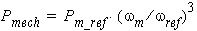
where Pm_ref is the turbine power with MPPT at a reference speed of wref based on the optimal tip speed ratio, and wm is the rotor speed in rad/s.
The rotor mechanical loss is
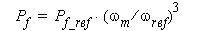
where Pf_ref is mechanical loss measured at a reference speed of wref.
The electromagnetic power in the air gap is
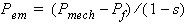
Therefore, the stator output electrical power at rated operation is:
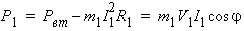
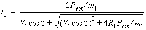
where m1 is the number of phases of the stator winding, R1 is the stator phase resistance, V1 is the stator rated phase voltage, I1 is the rated stator phase current to be determined, and cosᵩ is the rated power factor. Solving for I1 , one obtains:
Then, based on the equivalent circuit shown below, one obtains:
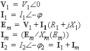
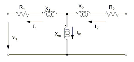
Now, rotor input electrical power can be computed as
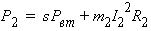
where m2 is the number of phases of the rotor winding.
The electromagnetic torque Tem is

where w denotes the synchronous speed in rad/s.
The input mechanical torque on the shaft is
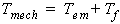
where Tf denotes the frictional torque.
The total electrical output power is
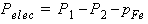
where pFe is the core loss.
The efficiency is defined as