DCMCore UDP
The DCMCore UDP is used to create a stator core with or without a compensating winding, a shunt and/or a series field winding, and a commutating pole with a commutating winding for DC machines. It can also create coil terminals for all windings for current assignment.
|
Property |
Description |
|
DiaGap |
Core diameter on gap side, DiaGap < DiaYoke for outer cores. |
|
DiaYoke |
Core diameter on yoke side, DiaYoke < DiaGap for inner cores. |
|
Length |
Core length |
|
Skew |
Skew angle in core length range |
|
FrameWidth |
Overall width of a racetrack frame |
|
FrameThick |
Frame thickness |
|
FrameLength |
Frame length |
|
Poles |
Number of poles |
|
PoleType |
Pole type: 1 to 2 |
|
Dmax |
Diameter of shoe tip with maximum air gap length |
|
Bp0 |
Pole arc width with uniform air gap; 0 for eccentric air gap. |
|
Bp1 |
Total pole width (the width between shoe tips) |
|
Bp2/Rp0 |
Bp2 (max shoe width for pole type 1), or Rp0 (shoe fillet radius for pole type 2) |
|
Bp3/Rp1 |
Bp3 (min shoe width for pole type 1), or Rp1 (pole fillet radius for pole type 2) |
|
Hp |
Pole body height |
|
Bm |
Pole body width |
|
FieldWndgs |
Number of field windings, 2 for both series and shunt windings. |
|
EndExt |
Coil one-side end extended length |
|
SlotsPerPole |
Compensating slots per pole distributed under pole arc surface |
|
Bc0 |
Opening width of compensating slots |
|
Hc0 |
Opening height of compensating slots |
|
Bc2 |
Width of compensating slots |
|
Hc2 |
Height of compensating slots |
|
CmpEndExt |
One-side end extended length of compensating coils |
|
ComPoleWidth |
Width of the commutating poles |
|
ComPoleHeight |
Height of the commutating poles |
|
ComPoleLength |
Length of the commutating poles |
|
ComShoeWidth |
Shoe width of the commutating poles |
|
ComShoeHeight |
Shoe height of the commutating poles |
|
ComShoeLength |
Shoe length of the commutating poles |
|
ComGap2 |
Air gap length between commutating poles and the frame |
|
CmtEndExt |
One-side end extended length of commutating coils |
|
LenRegion |
Region length |
|
InfoCore |
0: core & coils; 1: poles; 2: frame; 3: com poles; 4: shunt coil; 5: series coil; 6: com coil; 100: region |
|
Info Term |
0: whole coil; 1: terminal1; 2: terminal2 |
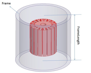
The DC Machine core is complex compared with other UDPs. When creating a DCM core in a Maxwell 3D design, it looks at first like the following figure in the coordinate system window.
Initial DCM Core
In order to better describe the parameters in this UDP, a slot core was added inside the DCM core and their lengths were set to be 0. Also the DiaGap of slot core was changed to 92 to show the air gap between two UDPs. The model now looks like the following example:
DCM Core Sheet (gray) with Slot Core Sheet (red)
The following figures show two different overviews of the gray, transparent DCM core and the referencing red slot core from different angles.
Transparent DCM core (gray) with Slot Core from different angles
![]()
Transparent DCM core (gray) with Slot Core from different angles
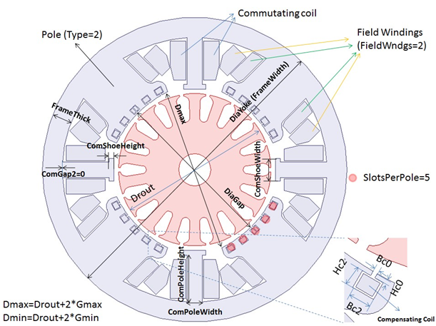
The following figures show the parameters of a DCM core.
- A slot core in red is drawn as reference.
- Because the structure of a DCM core is complicated and there are many parameters, figures are drawn using different InfoCore values of DCM core UDP to clearly describe parameters.
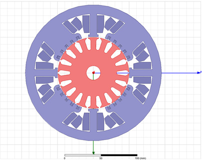
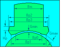
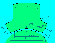
- Parameters of PoleType 1 and Parameters of PoleType 2 show parameters of two different pole types in the DCM core UDP. In these two figures, Bp0 is not 0, whereas in Parameters of DCM Core on 2D plane, Bp0 is 0, which means the air gap is eccentric.
- Dmax, by definition, is the diameter of shoe tip with maximum air gap length, which means Dmax=Drout+2*Gmax. “Drout” means the outer diameter of the rotor (which means DiaGap of slot core in this example and is shown in Parameters of DCM Core on 2D plane), and “Gmax” is the maximum air gap between poles and rotor, which is shown in Parameters of PoleType 1 and Parameters of PoleType 2.
- Correspondingly, there is Dmin (which is called DiaGap in DCM UDP and Parameters of DCM Core on 2D plane) and Gmin. Their relationship is Dmin=Drout+2*Gmin. They are also shown in Parameters of PoleType 1 , Parameters of PoleType 2, and Parameters of DCM Core on 2D plane.
- The value of ComGap2 in Parameters of DCM Core on 2D plane is 0, whereas it is positive in Parameters of a commutating pole (when ComGap is non-zero). In order to make the value of ComGap2 larger than 0, make sure to reserve enough space for ComGap2. This can be done by reducing the value of ComPoleHeight or ComShoeHeight or both.
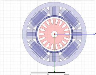
Parameters of DCM Core on 2D plane
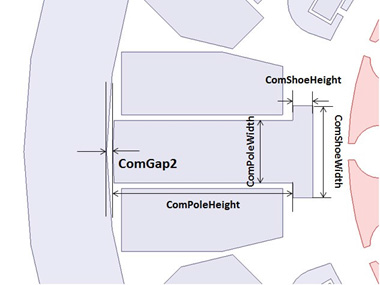
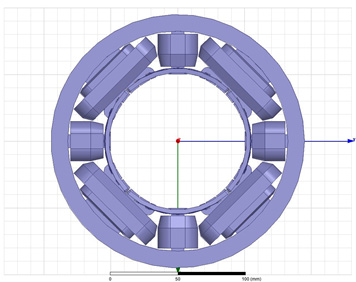
Parameters of a commutating pole (when ComGap is non-zero)
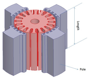
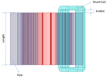
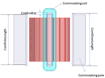
Axial parameters of poles and field windings