Customizing Ansys Electronics Desktop Menus
Ansys Electronics Desktop comes with a default menu bar. You can modify the default menu bar by using customized User Interface (UI) setups to add, remove, rename, and relocate commands. You can also add commands that execute external scripts or configure right-click menus for folders and items in the Project Manager Tree, which allows for extensive customization of the Ansys Electronics Desktop menus.
Customized setups are implemented using named subfolders that contain XML files used to configure customized menu settings. The subfolders included with Ansys Electronics Desktop are
- //config/UI/ElectronicsDesktop/EM
- //config/UI/ElectronicsDesktop/RF
- //config/UI/ElectronicsDesktop/RF.0
- //config/UI/ElectronicsDesktop/SI
- //config/UI/ElectronicsDesktop/SI1.0
- //config/UI/ElectronicsDesktop/SI2.0
- //config/UI/ElectronicsDesktop/Twin Builder
Each customized setup has its own subfolder. Within these subfolders, XML files hold the menu configurations as well as the right-click menus for that setup.
Select Different UI Types
To change the menu display from the default UI to a different UI type:
- Click Tools > Options > General Options > General > Desktop Configuration.
- Choose the UI type that you wish to use from the Custom Menu Set drop-down menu, and click OK.
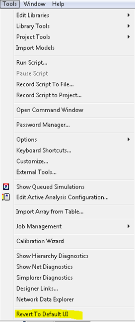
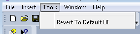
To switch from a customized UI type to the default UI:
- Click Tools > Revert To Default UI.
Add a New Customized UI Type
A new folder needs to be added to the //config/UI/ElectronicsDesktop folder for any new customized UI type. All XML files for this UI type must go in this folder. The new UI type will appear in the Custom Menu Set drop-down menu (Tools > Options > General Options > General > Desktop Configuration).
For any UI type, Ansys Electronics Desktop displays the default UI menus for any products/contexts that are not in the xml files. If there is error processing any XML file, the default UI menu is displayed for that product. Check the message window for the names of problematic XML files and suggestions on how to fix them.
XML files are only processed once when you first switch to that UI type. After you make changes to any XML file, in order for it to be reprocessed, navigate to Tools > Options > General Options > General > Desktop Configuration and reselect the UI type from the Custom Menu Set drop-down menu. Then click OK.
Names of the XML Files
Below is the list of XML files that can be placed in a folder for a new UI Type. If any of these XML files does not exist in this folder, the default menu setting displays for that product.
- 2D Extractor.xml – used for 2D Extractor projects.
- Circuit Design.xml – used for Circuit Design projects.
- Circuit Netlist.xml – used for Circuit Netlist projects.
- HFSS 3D Layout Design.xml – used for HFSS 3D Layout Design projects.
- HFSS.xml – used for HFSS projects.
- HFSS-IE.xml – used for HFSS-IE projects.
- Icepak.xml – used for Icepak projects.
- Maxwell 2D.xml – used for Maxwell 2D projects.
- Maxwell 3D.xml – used for Maxwell 3D projects.
- Maxwell Circuit.xml – used for Maxwell Circuit projects.
- Mechanical.xml – used for mechanical projects
- NoDesignUI.xml – used for menu settings when no project is selected.
- Q3D Extractor.xml – used for Q3D projects.
- RightClickMenu.xml – used for all right-click menu settings.
- Twin Builder.xml – used for Twin Builder projects.
Valid XML Elements and Attributes
- Root Element is
DesignerMenu:xmlns– required attribute which needs to be set to the following:<DesignerMenu xmlns="http://www.ansys.com/uiConfigMenu">UseProjectWindowSelectionContext– child ofDesignerMenu, appears zero or one time.Note: This is only meaningful if it is used in NoDesignUI.xml. If this is set totrue, then clicking in the Project Manager window on the Project icon or the Definitions icon (or a subitem) will show “Project” context in NoDesignUI.xml instead of active design context. No setting or setting this to false makes this UI type behave the same as the default behavior of Ansys Electronics Desktop. The menus and toolbars are always shown for the active design unless there’s no design at all.Context– child ofDesignerMenu. It appears at least one time and has a requirednameattribute. For details on setting the context name, see the Context Name section below.
- Child elements of
Context:TopMenu– For RightClickMenu.xml, do not use this element. You can specify child elements ofTopMenulisted below underContext. For any other xml files, you need at least oneTopMenuchild element for anyContext.Child elements of
TopMenu:MenuName– required, appears only one time.popupMenu– may appear one or multiple times; child elements are the same as those ofTopmenu.LeafMenu– may appear one or multiple times.Child elements of
LeafMenu:MenuName– optional string.Pay attention to the character reference
&in XML. In order for the name of the menu to be displayed as Tools, the XML syntax must be:<MenuName>&Tool</MenuName>&is the character reference for&in XML, while&Tooltells Ansys Electronics Desktop that Alt+T is the shortcut key for this menu.MenuID– optional number.For a list of valid MenuIDs, see Command IDs for Customizing AEDT Menus.xlsx under <install_dir>/v<release_number>/[Win64 or Linux64]/Help.
ShowBitMap– optional,“Yes”or“No”(default)Accelerator– optional string (Example: Ctrl+N)
CustomMenu– may appear one or multiple times; used to add a customized menu to run an external script (vbs or Python).Child elements of
CustomMenu:MenuName– see LeafMenu for UsageShowBitmap– see LeafMenu for UsageAccelerator– see LeafMenu for UsageScriptPath– required string; used to supply path to the script (use of$PROJECTDIR,$PERSONALLIB,$USERLIB,$SYSLIBvariables is also allowed).Example:
<ScriptPath>C:/Users/jw/Python/HelloWorld.vbs</ScriptPath>or
<ScriptPath>$PERSONALLIB/HelloWorld.py</ScriptPath>
Note: To add a newCustomMenu, bothMenuNameandScriptPathare required.Separator– may appear one or multiple times; has no child element.
Note: To add a newLeafMenu, both MenuName andMenuIDare required.
- All elements have an optional attribute of
action. Valid values areadd– can be applied to all elements other thanDesignerMenuorContext. This element and all its child elements will be added to its parent. An optional attribute ofpositioncan be followed here to specify the position of this newly added menu. Position starts from 1. If no position is specified, this menu will be appended to its parent menu.useDefault– default menus will be used for this menu(matched byMenuNameorMenuId). Any of its child menus will be processed according to its action setting.delete– can be applied to all elements other thanDesignerMenuorContext. This menu (matched byMenuNameorMenuID) will be deleted from its parent.
Note:- For
DesignerMenuandContext, only no action setting or“useDefault”is valid. - The
DesignerMenuaction setting is significant because it is how you specify whether you want to construct your own menus or modify existing default menus. If this is set to“useDefault”, default menu settings are used for any menus not listed in your XML files. If no action is set, only the File, Window, and Help menus display; no other default menus display. Menus listed in the XML file display after the File menu and before the Window menu. In this case, no action is needed for any other elements in the XML file. If any action is specified for any element, you will receive an error message and a default menu will be displayed for that context. A Revert To Default menu will be appended to the Tools menu. If no Tools menu is specified as a TopMenu, a Tools menu is created before the Window menu with one Revert To Default menu item. - For any other elements, a missing action setting means that the parent action will be used.
- If any element’s action is set to
“add”, then no action is needed for any of its child elements. If any action is specified, it will be ignored. This menu and all of its child menus will be added to the default menu. - If any
TopMenuorpop-upMenu’s action is set to“delete”, you don’t need to list any of its child menus. The menu will be deleted with all child menus.
- The
nameattribute specifies the name of the context for this product. You can have an"All"context if you set the action of DesignerMenu toUseDefaultto specify a menu setting that you want to apply to all contexts for that product. - Valid context name for different xml files:
- 2D Extractor.xml —
“All”,“3d modeler”,“report2d” - CircuitDesign.xml —
“All”,"SchematicEditor",“Layout”,“Netlist”,“report2d” - Circuit Netlist.xml —
“All”,“Design”,“Netlist” - HFSS.xml —
“All”,“3d modeler”,“report2d” - HFSS 3D Layout Design.xml —
“All”,“Design”,“Layout”,“Layout3D Editor”,“report2d” - NoDesignUI.xml —
“All”,“No Context”,“project”,“FilterDesign” - Q3D Extractor.xml —
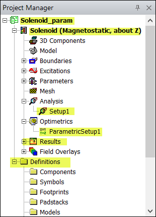
“All”,“3d modeler”,“report2d” - RightClickMenu.xml — The following figure illustrates valid context names and how they display in Ansys Electronics Desktop:
-
Project Folder –
"Project"; in the above figure,“Project”represents the Solenoid_param project folder. -
Design Instance Folder –
“Magnetostatic”,“Eddy Current”,“Transient”,“Electrostatic”,“AC Conduction”,“DC Conduction” -
Definitions Folder –
“Definitions”; in the above figure, the Definitions folder is highlighted. -
For any Folder or Item under the Design Instance or Definitions folder, use the “/” notation to specify the path to the Folder or Item for context name. In the above figure: Use “
Magnetostatic/Results”for the Results folder. -
For any folder or item under this, use the context name for the folder appended with
/Item. In the above figure,“Magnetostatic/Analysis/Item”represents Setup1, and “Magnetostatic/Optimetrics/Item”represents ParametricSetup1.
/Report; for example: "Magnetostatic/Results/Report".For the Trace folder under Report, use the context name for the Report appended with /Trace; for example: "Magnetostatic/Results/Report/Trace".
Sample XML Files
- Circuit Netlist.xml Sample
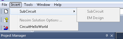
- Circuit Design.xml Sample
<DesignerMenu xmlns="http://www.ansys.com/uiConfigMenu">
<Context name="Design">
<TopMenu>
<MenuName>Insert</MenuName>
<pop-upMenu>
<MenuName>S&ubCircuit</MenuName>
<LeafMenu>
<MenuName>&SubCircuit</MenuName>
<MenuID>55500</MenuID>
<ShowBitMap>No</ShowBitMap>
<Accelerator></Accelerator>
</LeafMenu>
<LeafMenu>
<MenuName>&EM Design</MenuName>
<MenuID>55502</MenuID>
<ShowBitMap>No</ShowBitMap>
<Accelerator></Accelerator>
</LeafMenu>
</pop-upMenu>
<Separator></Separator>
<LeafMenu>
<MenuName>Nexxim Solution &Options ...</MenuName>
<MenuID>38460</MenuID>
<ShowBitMap>No</ShowBitMap>
<Accelerator></Accelerator>
</LeafMenu>
<CustomMenu>
<MenuName>CircuitHelloWorld</MenuName>
<ScriptPath>$USERLIB/HelloWorld.vbs</ScriptPath>
<ShowBitMap>No</ShowBitMap>
</CustomMenu>
</TopMenu>
</Context>
</DesignerMenu>
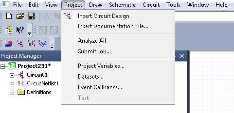
Menus created by processing the above sample, Circuit Netlist.xml
<?xml version="1.0" encoding="UTF-8" standalone="no" ?>
<DesignerMenu xmlns="http://www.ansys.com/uiConfigMenu" action="useDefault">
<UseProjectWindowSelectionContext>false</UseProjectWindowSelectionContext>
<Context name="All">
<TopMenu>
<MenuName>&Project</MenuName>
<LeafMenu action="delete">
<MenuName>Insert HFSS Design</MenuName>
</LeafMenu>
<LeafMenu action="delete">
<MenuName>Insert HFSS 3D &Layout Design</MenuName>
</LeafMenu>
<LeafMenu action="delete">
<MenuName>Insert Q3D Extractor Design</MenuName>
</LeafMenu>
<LeafMenu action="delete">
<MenuName>Insert 2D Extractor Design</MenuName>
</LeafMenu>
<LeafMenu action="delete">
<MenuName>Insert Circuit &Netlist</MenuName>
</LeafMenu>
<LeafMenu action="add">
<MenuName>Test</MenuName>
<MenuID>3333</MenuID>
</LeafMenu>
</TopMenu>
</Context>
</DesignerMenu>
Menus created by processing the above XML sample, Circuit Design.xml