Creating a Non-Salient Pole Core with a Q-Axis Damper
In general, this process is realized by a subtraction of two objects. Several steps are needed to finish the procedure.
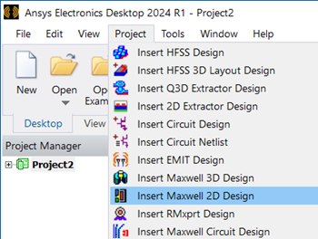
- Click Project > Insert Maxwell 2D
Design to create a Maxwell 2D Design in a project.
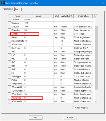
- Click Draw > User Defined Primitive > RMxprt > NonSalientPoleCore to draw a Non-Salient Pole Core UDP. In order
to show it in a 2D dimension, set the Length to 0. Also set AxialDucts
to 0 for subtraction, as shown in the following figure.
- Create a damper. Make a copy of the NonSalientPoleCore,
and then paste it and rename it to damper.
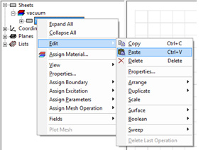
Rename the new NonSalientPoleCore to Damper:
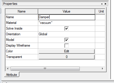
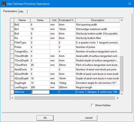
- Change the InfoCore value to 1
to make a damper. Also change the Color of the damper to distinguish
it from the NonSalientPoleCore.
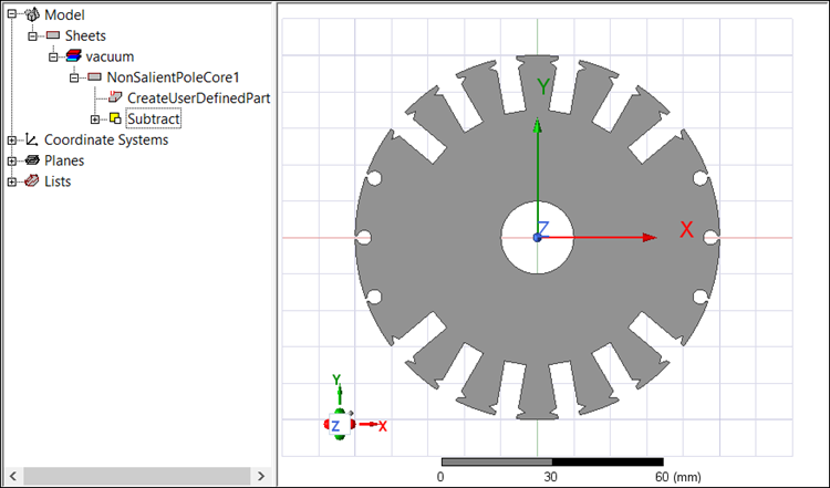
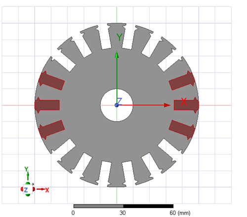
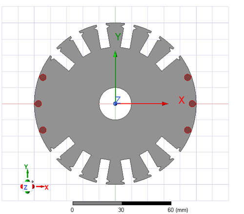
The objects appear as follows in the coordinate system window. The Non-Salient Pole Core is gray, and the damper is red.
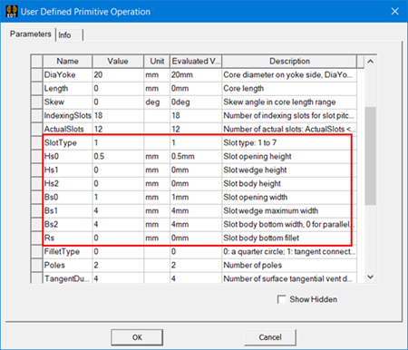
- You can also change the damper’s SlotType
and slot parameters if necessary. For instance, SlotType is reset
to 1 and slot parameters are reassigned as in the following figure.
After you modify the slot-related parameters of the damper, the objects in the coordinate system window appear as in the following example:
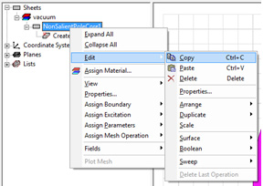
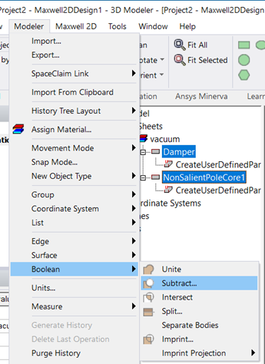
- Select both objects (Damper and NonSalientPoleCore)
in the history tree simultaneously by pressing Ctrl on the keyboard.
Click Modeler > Boolean > Subtract. A Subtract window appears.
- Move NonSalientPoleCore to Blank Parts and Damper to Tool Parts, and check the Clone tool objects before operation box. Click OK to finish subtraction.
![]()
The final history tree and coordinate system window show the objects after subtraction: