
Conductance Matrix for a 3D DC Conduction Solution
The Maxwell 3D conductance matrix relates the currents and the voltages as

Or in more concise form:

where
- I is conduction current,
- G is conductance, and
- V is voltage
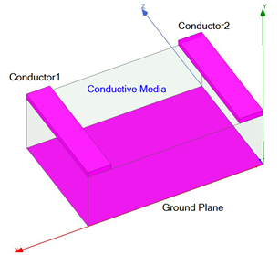
For a simple two-conductor system with a ground plane (V=0), where there are conductive media in the middle: Referring to the figure below, the current flowing through Conductor1 and Conductor2, I1 and I2, are related to their voltages V1 and V2 as
I1=G11*V1+G12*V2
I2=G21*V1+G22*V2
Maxwell 3D can also handle designs that have disconnected conducting regions (multiple, singly connected regions).
The relationship between the Maxwell conductance matrix GM and the Spice conductance matrix GS is:
-
GMi,i = GSi,1 +GSi,2+GSi,3+…+ GSi,n (i = 1,2,…,n)
-
GMi,j = - GSi,j (for i not equal to j)
A ground reference is needed for extracting this matrix. For the Maxwell 3D DC conduction solver, the “sink” excitation, which can be assigned only to surfaces, will be treated as ground. If there is no sink excitation, you must explicitly choose at least one "ground" from the list of voltage excitations in the parameter matrix dialog box.
In the conductance matrix extraction, if there are n “signals” (which can be associated with 3D volume body or 2D sheet body), each one of the n signal ports will be excited with 1 volt while leaving the other signal ports at 0 volt (the ground will be kept at 0 voltage). After calculating the solutions for the excitation settings, losses are computed using the entries of the Maxwell conductance matrix GM.