Coil Terminals
A coil terminal excitation is the preferred excitation for Maxwell transient applications. This type of excitation can be specified as functional (arbitrary functions of time) and is very flexible; six different combinations can be used: current, voltage, and external circuit, with either solid or stranded conductor options.
The current, stranded conductor option should be used when setting coils of constant cross-section made of strands of wire (with no eddy current effects to be taken into account in the coil). The current can be functional and the specific variation as a function of time can be specified by the user.
When defining the function, already defined primitives
such as sin(), cos(), exp(), etc. can be used. For arbitrary variations,
a piecewise linear capability can also be used by defining the corresponding
dataset. You should also specify the number of winding turns.
The current, solid conductor option does not carry the restriction of constant a cross-section. The current path can have varying cross-section, and can also split as long as in the end all parallel branches merge into a unique current path. You can also define a functional excitation and apply it to the winding.
The voltage, strand option is similar to the corresponding current setting, with the obvious difference being that now the voltage is known, while the current remains unknown. In many situations when the voltage setup is used, other terminal characteristics that influence the current calculation are also specified: for instance, series resistance, inductance, and capacitance. No eddy current effects are taken into account, so a series resistance (DC resistance) must be specified. For this type of source, the cross-section of each conductor needs to be constant, but the cross-section can differ from one coil to another, and it is possible to construct windings using coils with different cross-sections. After the solver calculates the total current, the current is uniformly distributed on the cross-section, as it always is with a stranded option.
The voltage, solid option is chosen when solid conductors with eddy effects are part of the winding. In this situation, eddy current effects are taken into account. If required by the application, you should also include other characteristics of the source, such as series resistance, inductance, and capacitance.
The external strand and external solid settings are used when the circuits attached to the windings have an increased degree of complexity. In the case of external sources, solid or stranded options are used, depending on whether or not eddy effects are to be taken into account.
There are normally two phases in the process of defining windings.
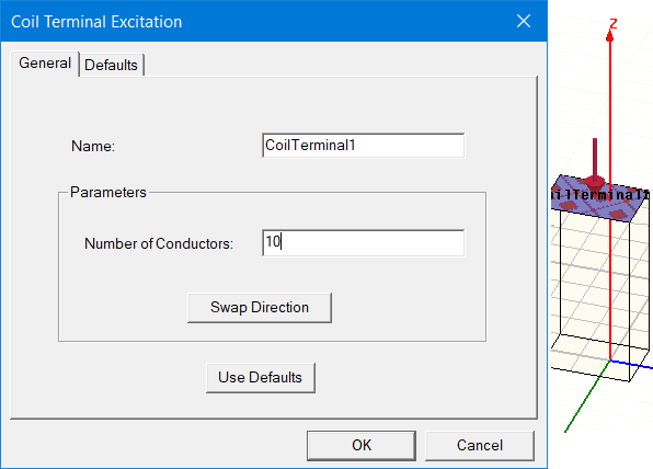
- First, define the terminal(s) by selecting
the planar surface(s) as appropriate for the model, and then assign the
coil terminal excitation by specifying the orientation of the current
with respect to the terminal (current in or current out, graphically
represented by an arrow). Specify the actual
number of conductors (turns) intersecting the
chosen planar surface (coil terminal), regardless of the symmetry
(if any) of the problem.
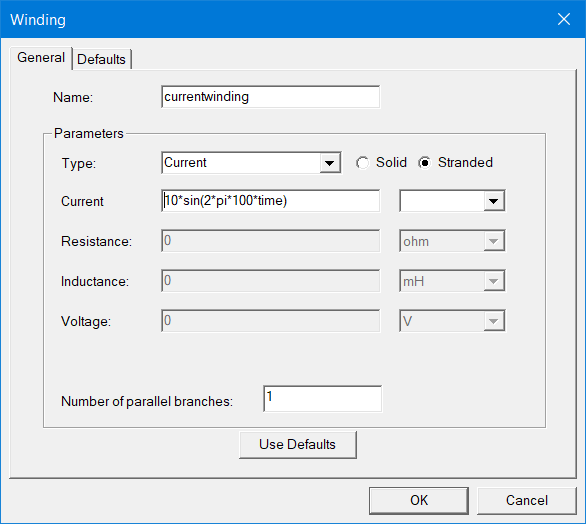
- Right-click in the 3D Modeler window, add a new winding from the excitation menu (no need to select any geometry), and specify the remaining details of the setup (the screen shot below shows a sinusoidal current with 10 A amplitude and 100 Hz frequency being used in the setup.
- Right-click the winding in the property window, and specify the coil terminal(s) that belong to the winding (unassigned coil terminals are listed and can be selected from the respective window).