Coil Connections
Connection of Double-Layer Lap Windings
Every vector represents the top-layer effective side of a coil. The bottom effective side of the coil is determined based on the coil pitch, and is not displayed in the diagrams. Therefore, every vector in the diagrams can also stand for a coil. Connect all coils in phase spread of A in positive direction, and all coils in phase spread of –A in negative direction to form the phase A winding. In this way, phase B and C windings can also be connected. The winding connection layouts for the vector diagrams are shown below.
Connection of Single-Layer, Half-Coiled Windings
Every vector in A, B and C phase spread represents "go" effective side of a coil, the "return" effective side of the coil is located in –A, –B and –C phase spread. For the lap type connection, all coils are with full coil pitch. The connection layouts of the lap type and the concentric type, with respect to the same vector drawing are shown below.
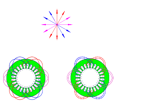
Connection of Single-Layer, Whole-Coiled Windings
In the previous example, for the concentric type (lower right in the diagram), if coil 1 is not connected from slot 1 to slot 8 (long coil pitch: coil pitch = 7 > pole pitch = 6), but connected from slot 1 to slot 20, and slot 8 to slot 13, all coils of phase A winding have coil pitch of 5. In this way, the winding becomes single-layer whole-coiled type with the same star vector diagram and phase spread, and has much shorter average coil pitch. Therefore, single-layer whole-coiled windings consume less electromagnetic wire than single-layer half-coiled windings. RMxprt can optimize connections to minimize the average coil pitch to form a single-layer whole-coiled winding.
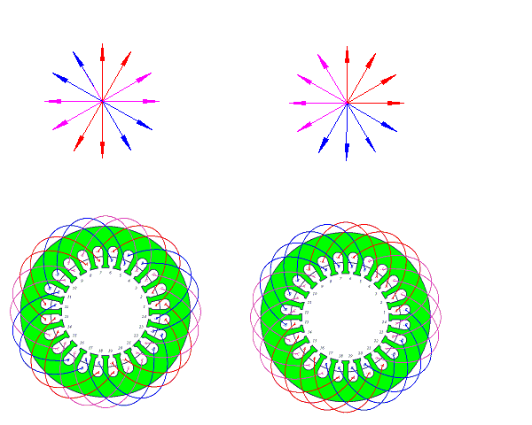
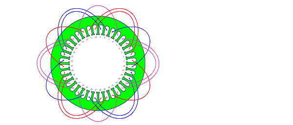
An example of three-phase, four pole, 36-slot ,single-layer, whole-coiled, crossed lap-type winding (q = 3, 60o phase-spread) is shown below.
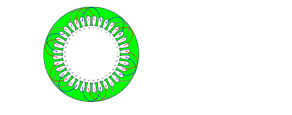
An example of three-phase, four-pole, 36-slot, single-layer, whole-coiled, crossed concentric-type winding (q = 3, 60o phase-spread) is shown below.
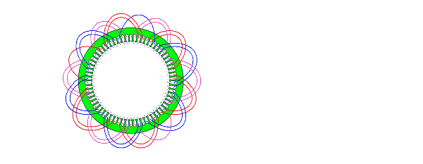
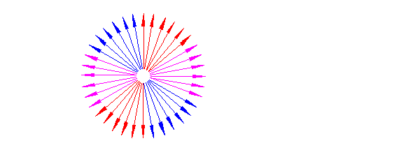
A star vector diagram with fractional coil pitch can also be connected with single-layer whole-coiled type. When the number of slots per pole per phase q <2, as shown in the following vector diagram, the number of coil sets per phase may not equal to the number of poles (6 coils vs 10 poles), but the algorithm to connect coils is the same (minimize the average coil pitch), and therefore, it is still referred as whole coiled windings.
The winding connection layout for the previous vector diagram is shown below.
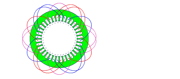
Another example is an asymmetric three-phase winding. The connection layout is shown below.