
Coil Arrangement
Coil arrangement is completed by the following processes. First, draw the star vector diagram based on number of slots and number of poles. Then divide the whole region (360 electric degrees) to several phase spreads, which is derived from the number of phases and the winding type. Finally, assign all phase spreads to each phase in such a way that the axis of each succeeded phase lags by 360/m electric degrees (90 electric degrees for 2 phases).
Double-Layer Windings
Take a three-phase winding as an example. The width of phase spread of half-coiled winding is 360o / 3 = 120o, and the sequence of the phase spread is A, B, C. For whole-coiled winding, the width of phase spread is 180o / 3 = 60o, and the sequence of phase spread is A, –C, B, –A, C, –B, where the phase spread with negative sign is termed negative phase spread.
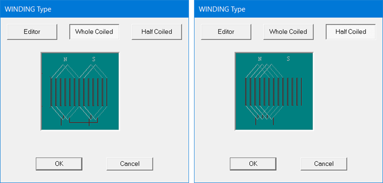
The winding types can be set in the Winding Type panel for a machine that includes these options (in this case, a brushless permanent magnetic DC motor), for double-layer whole-coiled windings as shown in on the left and double-layer half-coiled windings as shown on the right.
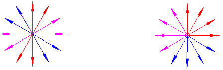
The star vector diagram of a three-phase, whole-coiled (60o-phase-spread) winding is shown below on the left, and that of a half-coiled (120o phase spread) winding is shown below on the right.
Single-Layer Windings
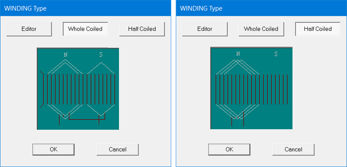
The winding layers can be set in the properties window for the winding, for single-layer, whole-coiled windings as shown on the left and single-layer, half-coiled windings as shown on the right.
The phase spread of a three-phase, single-layer, whole-coiled or half-coiled winding is 60o, and the star vector diagram is the same as the double-layer, whole-coiled winding.
Fractional-Pitch Windings
The number of slots per pole per phase of fractional-pitch winding is a mixed number.

In the unit electric machine, the numbers of slots occupied by phase spread are not all the same, but repeat with the radix d. In each d poles, there are c poles with the slot number of phase spread equal to b + 1 (big phase spread), d – c poles with the slot number of phase spread equal to b (small phase spread).
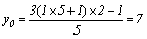
Take as an example a three-phase 10-pole 36-slot fractional-pitch winding with phase spread of 60°. The number of slots per pole per phase of fractional-pitch winding is

the greatest common factor between the number of slots 36 and the number of pole pairs 5 is t = 1, the angular phase difference between two contiguous vectors in the star vector diagram is

the difference between the ordinal numbers of the slots of two contiguous vectors is (G = 2)
the repetition radix d = 5. In each 5 pole region, each phase has big phase spread of 1 + 1 = 2 slots under 1 pole, and small phase spread of 1 slot under 4 poles. The repeating format is 2 1 1 1 1 for phase A. The repetition of phase spread distribution for all phases is shown in the following table.
|
Slot number |
1~2 |
3 |
4 |
5 |
6 |
7~8 |
9 |
10 |
11 |
12 |
13~14 |
15 |
16 |
17 |
18 |
|
Phase spread |
A |
–C |
B |
–A |
C |
–B |
A |
–C |
B |
–A |
C |
–B |
A |
–C |
B |
|
Slot number |
19~20 |
21 |
22 |
23 |
24 |
25 |
27 |
28 |
29 |
30 |
31 |
33 |
34 |
35 |
36 |
|
Phase spread |
–A |
C |
–B |
A |
–C |
B |
–A |
C |
–B |
A |
–C |
B |
–A |
C |
–B |
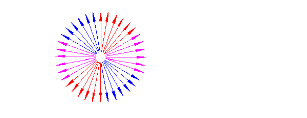
The star vector diagram of winding is shown below.
Asymmetric Windings
Whole-pitch windings (q is integer) are always symmetric. Fractional-pitch windings with

becomes asymmetric if the denominator d is a multiple of the number of phases m. In general, it is avoid using asymmetric windings as possible. Nevertheless, it is sometime possible to design poly-phase windings with little asymmetry in order to use existing punching tools.
If d is a multiple of the number of phases m, but the total number of slots Z can be divided by m, it is possible to construct poly-phase winding with little asymmetry. RMxprt can perform automatic arrangement for this sort of windings and obtain the phase-spread in electric degrees for each phase.
Take as an example a three-phase, six-pole, 66-slot, fractional-pitch winding electric machine. Because

d = m = 3, the winding is asymmetric. The output in the window Design Output is shown below.
The information for WINDING ARRANGEMENT is displayed as follows:
The distribution of coil slots to phases:
The 3-phase, 2-layer winding can be arranged in 66 slots as below:
AAAAZZZZBBBXXXXCCCCYYYAAAZZZZBBBBXXXCCCCYYYYAAAAZZZBBBBXXXXCCCYYYY
X, Y and Z stands for –A, -B and –C, respectively. For asymmetric windings, additional information is output, as shown below.
The winding factors of each phase are
|
Phase A |
0.954119 |
|
Phase B |
0.954119 |
|
Phase C |
0.949042 |
The angles between two-phase winding axes are
|
Phase A & B |
119.082 |
|
Phase B & C |
120.459 |
|
Phase C & A |
120.459 |
If a sinusoidal rotating field links the winding, the fundamental induced-voltage components will be
|
Positive-sequence component |
100% |
|
Negative-sequence component |
0.286577% |
|
Zero-sequence component |
0.639823% |