
Assigning a Band of Motion
You can assign a band of motion in both Maxwell 2D and Maxwell 3D projects. For both Maxwell 2D and 3D projects, two or more motion bands may be assigned.
For both rotational and translational problems, the band object must always enclose all of the moving objects. For rotational problems, this means the band object should be a solid cylinder or a solid wedge – not a hollow shell or segment of a shell. If the band object encloses all moving aspects, it is easier to identify the moving objects and reduces errors related to misidentifying them.
- The first is to avoid creating holes inside the band which would result in the band having multiple connected domains.
- The second is due to the torque/force computation being carried out by one layer of elements inside the band region that directly touches moving objects. If an inner region is not included, the torque/force computation will be very sensitive to mesh noise - thus leading to an inaccurate solution.
- An all-encompassing inner region (non-magnetic, non-conductive wrapper such as air or vacuum) must be used around all moving objects in a band.
- The inner region wrapper object, like the Band itself, should be a simplified shape, such as a rectangle or polygon in 2D, or a polyhedral or segmented sweep section in 3D. Any simplifications to the inner region and band object will result in better re-meshing for each time-step and faster overall simulation times.
- In order to give more accurate forces, if there is sufficient clearance between moving and stationary objects, you can provide some padding between the inner region and the moving objects and the band. At a minimum, the inner region should be the same size as the outside of the enclosed objects (like shrink wrap) with no gap between the wrapper and objects inside.
- Ansys highly recommends that the band not touch any outer stationary objects, with the only exception being for symmetry boundaries on the outer region. It is suggested to locate the band halfway in the air-gap between fixed and moving objects or equally spaced with the inner region object if there is sufficient clearance at the gap.
- In order to get stable force results, length-based mesh operations (approximately equal to the distance between the band and the inner region) should be applied using the Length-Based-Inside mesh refinement assigned to the Band object so that the mesh length is refined in the band region that is re-meshed for each time-step.
To assign the band of motion:
- Select the band object.
- Click Maxwell > Model > Motion Setup > Assign Band.
- On the Type tab: select either Translation or Rotation as the Motion Type.
- For Rotation about a fixed point you may select the Non-Cylindrical check box.
- For Translation, you may select the Periodic check box.
- Set the motion direction:
- For Translation (including Periodic), select the desired X, Y, or Z (for 3D) axis of motion from the Moving Vector drop-down menu; then select either Positive or Negative direction.
- For Rotation, from the Moving
Axis drop-down menu, select an axis of rotation. Use the radio buttons
to select either Positive or Negative rotation.
Note:
- For 2D XY rotation, only Positive rotation is allowed.
- If the expected moving vector does not exist, click Modeler > Coordinate System > Create > Relative CS to create a new coordinate system.
- On the Data tab: type a value in the Initial Position box, and select the units from the drop-down menu.
- To set the motion limits, do the following
in the Translate Limit or Rotate Limit section:
Note: For Periodic motion, you do not need to define motion limits because the solver does not consider the limits for periodic motion; thus the Translate Limit section is not present.
- For rotational motion, click the Rotate Limit check box.
- For translational (non-Periodic) or rotational motion, type a value in the Negative box, and select the units from the drop-down menu.
- For translational (non-Periodic) or rotational motion, type a value in the Positive box, and select the units from the drop-down menu.
- On the Mechanical
tab, do one of the following to specify the object velocity (dynamic
or constant):
Note: When you select Consider Mechanical Transient, you are telling the solver to use the calculated force and user-specified mass, damping, and other parameters to dynamically determine how the object moves, rather than giving it a constant velocity.Note:
- For Maxwell 2D/3D designs for motor applications, the computed output mechanical power at given constant speed may not reach the desired rated power. Therefore, it is useful to apply constant power as the mechanical load. In Maxwell 2D/3D designs created by RMxprt, the mechanical transient is set up according to the rated mechanical output power, and equivalent damping is added to accelerate the process approaching to the rated output power. This setup is visible when Consider Mechanical Transient is checked.
- The Consider Mechanical Transient setup is only for the sake of getting the operating point with given output power. it is not related to any mechanical load type you may set in RMxprt.
- 2D/3D designs generated from RMxprt include the setup data, but Consider Mechanical Transient is unchecked initially. To ensure that the setup data is preserved, make sure that you check Consider Mechanical Transient before saving the project.
- To dynamically change how the object moves, click the Consider Mechanical Transient check box, complete the following fields, and select any corresponding units:
- Initial Velocity (translational) or Initial Angular Velocity (rotational)
- Mass (translational) or Moment of Inertia (rotational)
- For 2D problems, the moving bodies are assumed to be of model-unit thinness.
- Rotating bodies must be symmetric about the axis of rotation. Partial models (e.g., half a motor with implied symmetry) are not supported.
- Damping (rotational motion) – A value for damping for rotational motion (for electric machines) can be calculated by the windage and friction loss in Watts divided by the speed in rad/sec (at which those losses are defined); the resulting units are in W / (rad/sec)2 or N*m * sec/rad.
- Damping (linear motion) – A value for damping for linear motion can be calculated by the windage and friction loss in Watts divided by the speed in m/sec (at which those losses are defined); the resulting units are in W / (m/sec)2 or N*m * sec/m.
- Load Force
(translational) or Load Torque
(rotational)
Note:
- For translational motion, the load force is positive if it is applied in the same direction as the moving vector and negative if applied in the opposite direction.
- For rotational motion, the load torque sign is determined based on the moving vector, using the right-hand rule. Point your thumb in the direction of the moving vector. If the load torque is applied in the same direction as your fingers, then the load torque is positive. If it is applied in the opposite direction, then the load torque is negative.
- To set a constant velocity (and disable the mechanical transient), clear the Consider Mechanical Transient check box, type a value in the Velocity or Angular Velocity box, and select the units from the drop-down menu.
- For translational motion, a Post-Processing tab is available to set the coordinate system for post processing calculation.
- Click OK.
The Motion Setup window appears.
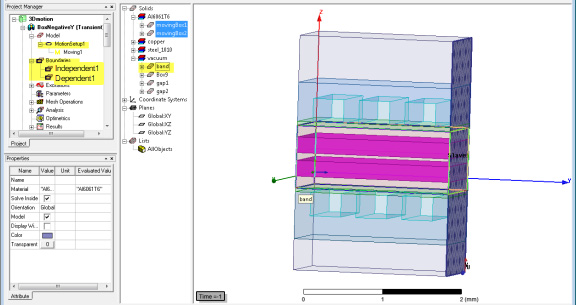
For Periodic motion, you must define independent and dependent boundary conditions. Both band and the object(s) inside it move, and both should touch the independent and dependent boundaries as shown in the following example.
Use the Calculate button to have Maxwell calculate the Mass or Moment of Inertia with the following restrictions:
- A MotionSetupx is created and added to the Model folder in the Project Manager window.
- For Maxwell 3D projects only, if cylindrical Rotation was specified and a CylindricalGap mesh operation does not already exist, a CylindricalGap mesh operation is automatically added to the Mesh folder. Only one CylindricalGap mesh operation is permitted.
Related Topics
Non-Cylindrical Rotational Motion