
Analysis Approach for Three-Phase Synchronous Machines
The three-phase salient-pole synchronous electric machine has two types: the generator and the motor. Their basic structures are the same. Three-phase synchronous generators are the main source of electrical energy for industrial, commercial, and private use. They receive mechanical energy at the shaft and transform it into electrical energy. The rotor is equipped with a multipole winding excited by a DC source. The stator is equipped with a three-phase winding that has a sinusoidal spatial distribution. The spinning rotor produces a rotating magnetic field in the air gap of the machine. The frequency of the voltage induced in the stator is given by f=pv, where p is the number of pairs of poles, and v is the velocity of the rotor. The machine is capable of producing both active and reactive power as required by the load connected at the stator phasor.
The three-phase salient-pole synchronous electric machine has two types: the generator and the motor. Their basic structures are the same. Usually the frequency-domain phasor diagram is adopted to analyze the characteristics. The phasor diagram for a generator is shown on the left and that for a motor is shown on the right.
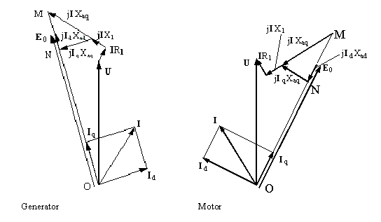
In the figure, R1, X1, Xad, and Xaq are armature resistance, armature leakage reactance, d-axis armature reactance, and q-axis armature reactance, respectively. Xad is nonlinear, while a linearized value is used in the phasor diagram. Taking the input voltage U as the reference phasor, for a given current:

where ᵩ is the power factor angle, a phasor represented by OM can be derived by U + I(R1 + jX1 + jXaq).
The direction of E0 can, therefore, be obtained. Taking the power angle, the angle that U legs E0, as θ, then the angle that I legs E0 is y = θ + ᵩ
The d- and q-axis currents are then represented by the following:
Id = I * sin(ψ)
Iq = I * cos(ψ)
The phasor length ON represents the d-axis back EMF from d-axis resultant flux linkage and is used to determine the d-axis field saturation. Then a frozen method is applied to derive E0, Xad, and exciting current If.
The output power (electric power) is directly computed from voltage and current as
P2 = 3*U*I*cos(ᵩ)
The input power (mechanical power) is defined as
P1 = P2 + Pfw + Pcua + PFe + Padd + Pcuf + Pex
where Pfw, Pcua, PFe, Padd, Pcuf, and Pex are frictional and wind loss, armature copper loss, iron-core loss, additional loss, field winding copper loss, and exciter loss, respectively.
The input mechanical shaft torque is T1 = P1/w, where w is synchronous speed in rad/s.
The efficiency is computed by eff = P2/P1 * 100%.
Main Features
- Adapted to both Synchronous Motor and Generator: The structures of the salient-pole synchronous motor and the generator are basically the same, but their phasor relationships and the computation methods are slightly different, their output characteristics data are also different. This is specified in the solution setup.
- Auto Arrangement of Three-phase Windings: Almost all commonly used three-phase single- and double-layer, half- and whole-type ac windings (including fractional-pitch windings) can be automatically arranged. Users do not need to define coils one by one. RMxprt also supports a double-layer winding with half-turn coils which are auto-arranged in the order of even, odd, even, odd, …, and even, odd, as long as it is physically possible.
When a designer adopts single-layer whole-coiled windings, RMxprt will perform winding arrangement optimization to minimize the average coil pitch. When asymmetric three-phase windings are used, winding arrangement is optimized in such a way that minimum negative-sequence and zero-sequence components are achieved.
- Winding Editor Supporting Any Single- and Double-Layer Windings: Besides taking advantage of the winding auto-arrangement function in RMxprt, users can also specify any special winding by using of the Winding Editor function.
In Winding Editor, through modification of phase belonging, number of turns, in-slot and out-slot number of each coil, it is possible to design single- and double-layer winding arrangement for any purposes.
- Analyze Air-Gap Magnetic Field Distribution: For both uniform and non-uniform air gaps, Schwarz-Christopher Transformation is adopted to solve for the air-gap magnetic field distribution.
- Analyze EMF Waveform and Total Harmonic Distortion (THD): Based on the analysis of the air-gap magnetic field waveform, taking into account coil short pitch, winding distribution, skew slot, winding connection, load effects and other factors, the emf waveforms in the coils and the windings are analyzed to solve for the emf distortion factors.
- Analyze Dynamic Parameters of Damping Winding: Different from the squirrel-cage winding of the induction machine, the damping winding of the salient-pole synchronous machine is located in the surface of magnetic field poles, which deviates greatly along the d- and the q-axes. Furthermore, the connection of damping bars has several forms. The bars under each pole could be connected, but not connected with those under other poles. All the bars could be connected together. The bars could be connected through the endplate. RMxprt can deal with all those complicated situations and give the dynamic parameters for the damping winding.