
Analysis Approach for Three-Phase Non-Salient Synchronous Machines
The three-phase non-salient-pole synchronous electric machine has two types: the generator and the motor. Their basic structures are the same. The three-phase non-salient-pole synchronous generators are the main source of the electrical energy for industrial, commercial, and private use. They receive the mechanical energy at the shaft and transform it into the electrical energy. The rotor is equipped with a non-salient-pole winding excited by a DC source. The stator is equipped with a three-phase winding that has a sinusoidal spatial distribution. The spinning rotor produces a rotating magnetic field in the air gap of the machine. The frequency of the voltage induced in the stator is given by
f =(pn)/60
where p is the number of pairs of poles, and n is the mechanical speed of the rotor in rpm, which is called the synchronous speed. The machine is capable of producing both the active and the reactive power as required by the load connected at the stator terminal.
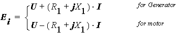
Usually the frequency-domain phasor diagram is adopted to analyze the characteristics. The phasor diagrams for a generator and a motor are shown.
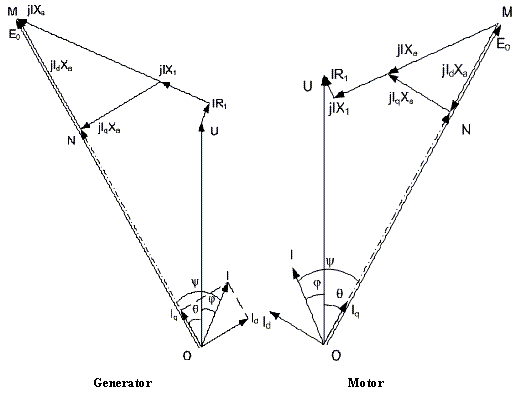
In the figure, R1, X1, and Xa are the armature resistance, the armature leakage reactance, and the armature reactance, respectively. In a non-salient-pole synchronous machine, Xad@Xaq and they are both expressed by Xa. Taking the input voltage U as the reference phasor, for a given current:
I = IÐ - ᵩ
where j is the angle I lags U , which is called the power factor angle.
The internal back EMF induced by the resultant air gap field considering the effects of armature reaction Ei can be derived from
Based on Ei, the resultant air gap flux considering the effects of armature reaction can be computed, and therefore, the magnetic circuit can be solved. With solved magnetic saturation factor, saturated Xa is derived, and therefore, the no-load induced voltage E0 with the same magnetic saturation (frozen magnetic circuit) can be calculated from:
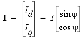
Let the angle U legs E0 be q, which is called the power angle for the generator or the torque angle for the motor, then the angle I lags E0 is
The d- and the q-axis currents can be obtained respectively as follows:
Based on the magnetic circuit solution and E0, Xa and the excitation current If can be determined based on the frozen method.
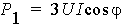
For the generator:
The output power (electric power) is directly computed from the voltage and the current as:
The input power (mechanical power) is defined as:

where Pfw, PCua, PFe, Padd, Pcuf and Pex are the frictional and wind loss, the armature copper loss, the iron-core loss, the additional loss, the field winding copper loss, and the exciter loss, respectively.
The input mechanical shaft torque is

where w denotes the synchronous speed in rad/s.
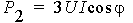
For the motor:
The input power (electric power) is directly computed from the voltage and the current as
The output power (mechanical power) is defined as:

where Pfw, PCua, PFe, Padd, Pcuf and Pex are the frictional and wind loss, the armature copper loss, the iron-core loss, the additional loss, the field winding copper loss, and the exciter loss, respectively.
The output mechanical shaft torque is

The efficiency is computed for both the generator and the motor by
