Analysis Approach for Switched Reluctance Motors
This motor type operates with shaft position feedback to synchronize the commutation of the phase currents with precise rotor position. Typically, both the stator and the rotor are salient to increase the torque-producing characteristics of the motor. The rotor has no windings; the torque is produced by the alignment tendency of the rotor to the stator so that the stator flux linkage is maximized.
In these motors, the stator and rotor have different numbers of poles. The stator phase windings are energized at precise moments synchronized with the position of the rotor. The task of energizing the stator windings is performed by a complex electronic system.
The number of phases in the winding is the ratio of the stator number of poles to the smallest common divider of the stator and the rotor number of poles.
In switched reluctance motors (SRM), the stator and the rotor have a different number of poles, and the stator currents are commutated exactly according to rotor position. The signal of the rotor position is obtained from a position sensor. The stator windings are triggered one by one, and normally the current in a winding has finished or almost finished freewheeling when the next winding is triggered. Therefore, the mutual effects between two phases can be neglected. The voltage equation of one phase is:

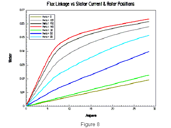
where uT is the transistor or diode voltage drop, and Rs is the stator winding resistance. Y(θ, i) is the flux linkage of the winding at rotor position θ and winding current i, as is shown in Figure 8, where the rotor position when the center of the rotor slot is aligned to the winding axis is defined as 0.
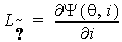
Let
and
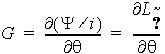
Then

where we is the rotor speed in electrical rad/s, and p is the differential operator as given by

The instant electromagnetic torque t2 is

The input electric power is computed from voltage and current as
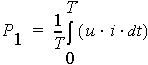
The output mechanical power is

where Pfw, PCua, Pt, and PFe are frictional and wind loss, armature copper loss, transistor/diode loss, and iron core loss, respectively.
The average output mechanical shaft torque T2 is

where w is the rotor angular speed in mechanical rad/s.
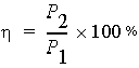
The efficiency of the electric machine is computed by