
Analysis Approach for Line-Start PM Synchronous Motors
Synchronous motors use a three-phase sinusoidal voltage source to induce a rotating magnetic field in the stator. Applying this three-phase sinusoidal voltage source to the stator winding of a synchronous motor yields the rotational magnetic field in the air gap. The permanent magnet poles mounted on the rotor try to align in this rotating field, producing a synchronous torque on the rotor. Upon starting, the damping winding on the rotor generates the asynchronous starting torque, creating a self-starting feature.
The phasor diagram for the line-start permanent-magnet synchronous motor (LSSM) in the frequency domain is shown in Figure 6.

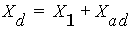
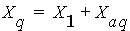
In Figure 6, R1, Xd, and Xq are armature resistance, d-axis synchronous reactance, and q-axis synchronous reactance, respectively. Xd is the sum of leakage reactance, X1 and d-axis armature reactance Xad, and Xq is the sum of X1 and q-axis armature reactance Xaq:
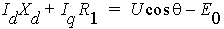
For a given torque angle q, the angle that E0 lags U:
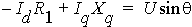
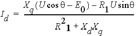
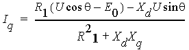
Solving for Id and Iq yields
The angle that I legs E0 is
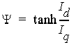
The power factor angle (or torque angle) that I legs U, is

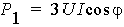
The input power (electric power) can now be computed from voltage and current as
The output power (mechanical power) is
where Pfw, PCu, and PFe are frictional and wind loss, armature copper loss, and iron-core loss, respectively.
The output mechanical power (torque) T2 is

where w is the synchronous speed in rad/s.
The efficiency is computed by
The motor is started the same way as for an induction motor, by using a squirrel-cage-type winding – called a damper winding in this case – that is mounted on the rotor, producing the starting torque.