
Analysis Approach for Brushless PMDC Motors
The stator of a brushless DC motor is equipped with a polyphase winding. The phases are connected to the DC bus through a switching circuit. The switching sequence is controlled so that it is synchronized with the position of the rotor. As a result, the stator produces a rotating magnetic field.
The rotor is equipped with permanent magnets, creating a structure with the same number of poles at the stator. The stator switches act like a commutator in a classic DC motor.
In brushless permanent-magnet DC (BLDC) motors, the armature currents are commutated exactly according to rotor position. The signal of rotor position may be obtained from a position sensor, or from induced voltages for sensor-less control system.
The performance of BLDC motors is analyzed via a time-domain simulation. The voltage equation in the time domain is
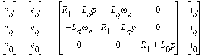
where R1, Ld, Lq, and L0 are armature resistance, d-axis synchronous inductance, q-axis synchronous inductance, and 0-axis inductance, respectively. we is rotor speed in electrical rad/s, and p represents for d/dt.
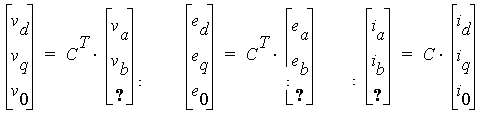
The transformations for terminal voltages, induced voltages, and winding currents are given by the following three equations:
The transformation matrices for 2-phase, 3-phase, and 4-phases systems, noted as C2, C3, and C4, are as follows:


where α = 2p/3.
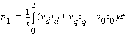
The input power (electric power) can now be computed from the voltage and current as
The output power (mechanical power) is
P2 = P1 - (Pfw + PCua + Pt + PFe)
where Pfw, PCua, Pt, and PFe are frictional and wind loss, armature copper loss, transistor/diode loss, and iron-core loss, respectively.
The output mechanical shaft torque T2 is T2 = P2 /w, where w is the rotor speed in mechanical rad/s.
The efficiency is computed by eff = P2/P1 * 100%