
Import an IDF File
Follow this procedure to import an Intermediate Data Format (IDF) files that have been exported from an ECAD package.
-
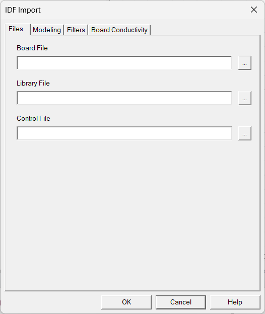
- On the IDF Import dialog box
- In the Open dialog box, browse to the location of the IDF files, select the board file, and click Open. If available, the Library File and Control File fields are automatically populated.
- If needed, click the button next to Library File and Control File to select these files.
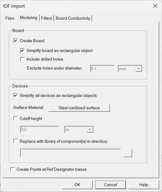
- On the Modeling tab, do the following if needed:
- Select Create Board to include board geometry. To import the board as a simple rectangular geometry, select Simplify board as a rectangular object. To import the board in its original polygonal shape, leave this field unchecked.
- Select Include drilled holes to import the board geometry with the drilled holes with air assigned as the material property. To filter out small holes that are not of interest, enable Exclude holes under diameter and specify the threshold diameter value and unit.
- Select Simplify all devices as rectangular objects to import all devices as simple rectangular pieces of geometry.
- Click the Surface Material button to open the Select Definition dialog box and select a surface material to assign to the devices.
- Select Cutoff height and enter a maximum height. Components with a greater height are cut off to the specified height.
- If needed, select Replace with library of component(s) in directory: to replace the imported model components with those components in the specified directory. A component in the specified directory replaces an imported model component when there is a match between the modified partNumber name in the IDF file and the component file name in the specified directory. Supported file types include .a3dcomp, .jptd, and JEP30 .xml. Part number names are modified to an Electronics Desktop group and part name using valid characters (letters, numbers, and underscores). Invalid characters are replaced by underscores.
- Select Create Points at Ref Designator bases to generate points in the 3D modeler window and History tree for each reference designator.
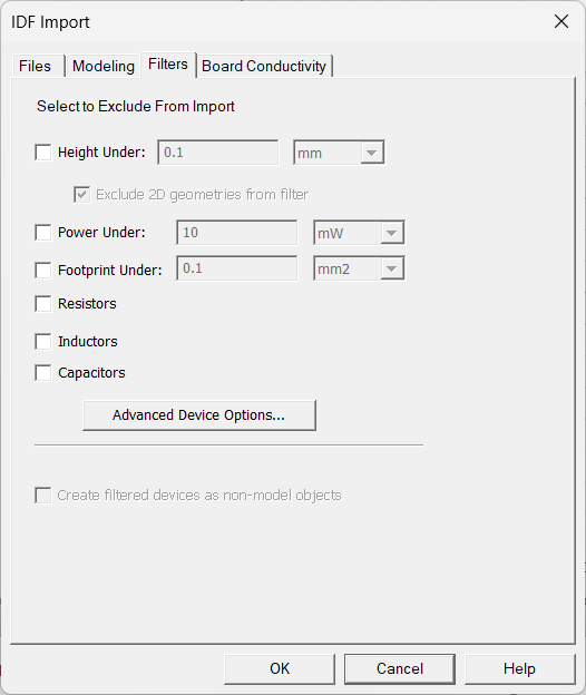
- On the Filters tab, select the check boxes of the filters you want to apply to the import.
- For Height Under, Power Under, and Footprint Under, specify the minimum height, power, and footprint of the components to be imported.
- If Resistors, Inductors, or Capacitors is selected, the corresponding components are not imported.
- If needed, click Advanced Device Options to override the thermal properties of devices and enable advanced filtering options.
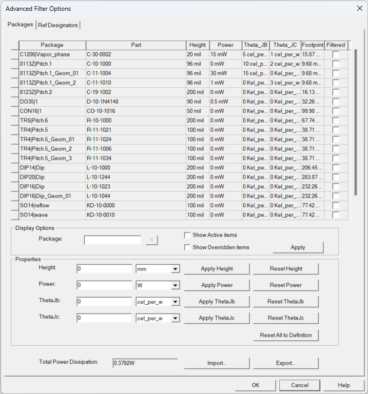
- The table at the top contains geometric and thermal model information of each package as available in the IDF file. The Packages tab contains per package data, while the Ref Designator tab contains data for all instances of each package. Below the table are the Display Options and Properties editing area.
- The Packages tab lists the Package name, the unique Part name, and the Footprint area, as input in the ECAD tool. These values can only be changed in the ECAD tool. Note that, other than the board, all objects in the IDF file, including logos and mechanical parts, are treated as a package.
- The remaining fields in the Packages tab are editable: Height, Power, Theta_JB, and Theta_JC. To edit any of these fields, first select the row corresponding to a package. Then, in the Properties area, enter new values for the Height, Power, ThetaJb, or ThetaJc fields. Finally, click the corresponding Apply button to update the value. The Reset buttons will revert the field values to those in the IDF file.
- The table can be sorted in ascending or descending order with any of the column titles as the sorting criterion, except the Filtered column. For example, toggle on the Footprint column title to sort the entire table in ascending or descending order of the package footprint areas.
- Packages selected in the Filtered column will not be imported into Icepak. Toggling the Filtered column title selects or deselects all packages.
- The Ref Designators tab lists all the instances of each package. This tab contains the additional information: reference designator under Ref Des, component Placement as the Top or Bottom side with respect to the board, and Model set as solid Block or 2R Network.
- The Ref Designators tab allows you to change the power values in any of the instances of a given package, while the unchanged instances follow the inputs given in the Packages tab.Note: Overridden height, power, theta jb, and theta jc values appear in orange text. To restore all original values, click Reset All to Definition.
- In the Display Options, the table in the Packages tab can be reduced to show only the active (unfiltered) packages. This reduces the list to the active packages in the Ref Designator tab as well. The same options also exist in the Ref Designators tab and similarly reduce the Packages table that is displayed.
Additional filter options are listed in the table below.
Display Options
Package
Enter a string of letters and/or numbers to displays rows containing those letters in the Package cell.
Show Active Items
Enable Show Active Items to hide rows with Filter enabled.
Show Overridden Items
Enable Show Overridden Items to show only rows whose height, power, thetajb, or thetajc properties have been overridden in the Properties area.
- To filter the items displayed in the Advanced Device Options table by device types, select the device type. The table below shows all the display filtering options by device types.
Display Options
Package
Enter a string of letters and/or numbers to displays rows containing those letters in the Package cell.
Ref Designator
Enter a string of letters and/or numbers to displays rows containing those letters in the Ref Des cell.
R, L, C, Others Enable R, L, and/or C to display rows beginning with the selected letter in the Ref Des cell. Enable Others to display rows beginning with letters other than R, L, or C. Top
Bottom
Enable Top and/or Bottom to display rows based on the Placement of the device. Apply Click Apply to filter by the selected display options. Show Active Items
Enable Show Active Items to hide rows with Filter enabled.
Show Overridden Items
Enable Show Overridden Items to show only rows whose power properties have been overridden.
- The Total Power Dissipation field below the Properties area shows the sum of power dissipations of all the component instances, which may be verified in the Ref Designators tab.
- The Export option allows saving all the changes made here into a tab-delimited (.tab) text file or a comma-separated value (.csv) spreadsheet file. If repeating this in future and the same inputs are desired, this file may be re-imported using the Import tab. Once exported, the files may be edited as long as the format remains the same, to enable a modified import.
- When finished, click OK to close the Advanced Device Options dialog box.
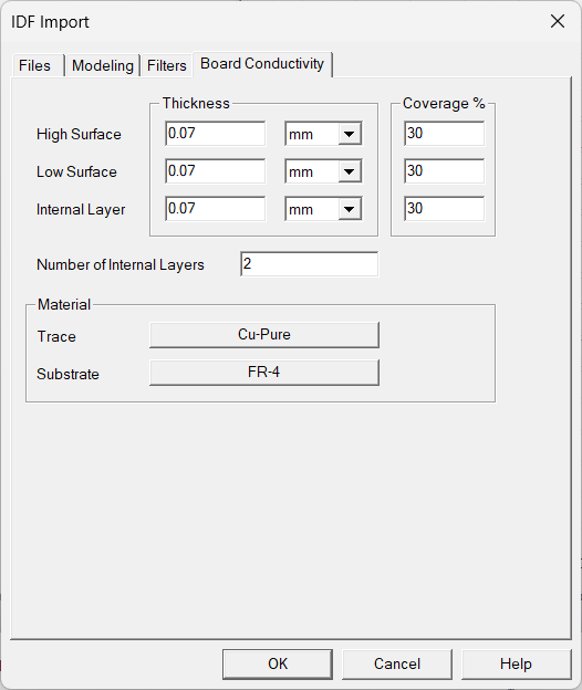
- If you enabled Create Board, do the following on the Board Conductivity tab:
- Enter Thickness and Coverage% for High Surface, Low Surface, and Internal Layer.
- Enter the Number of Internal Layers.
- Assign materials for Trace and Substrate.
- Click OK to import the model.
The File > Import > IDF option creates a new HFSS 3D Layout project and is not relevant in Icepak designs.
If needed, enable Exclude 2D geometries from filter to ensure that two-dimensional geometries, such as a 2D source, are imported.
Icepak thermal boundary conditions are automatically assigned after import based on the IDF data.