
Checking the Face Alignment
Face alignment is a measure of mesh quality defined by

where  and
and  are the centroids of two adjacent elements, and
  is the normal vector to the face between the two elements, as shown in the 2D example below.
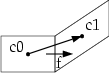
Adjacent mesh faces that are not aligned can result in long, narrow elements. A value of 1 indicates perfect alignment. Values less than 0.15 indicate a severely distorted mesh.
To check face alignment for the currently loaded mesh:
- From the Icepak>Fields menu, select Mesh Viewer.
-
Click on the Quality tab to show the mesh diagnostic tools.
- Select the Face alignment option. Icepak displays a histogram of the face alignment, as shown in Figure 1.Note:
By default, All is selected, which displays values for mesh within the entire global mesh region. Select Geometry selection to display values for geometry selected in the 3D Modeler window or history tree, including non-model boxes representing mesh regions.
-
To modify the range of face alignments viewed, enter a new value in the Min or Max field and then press the Enter key on your keyboard or click Apply to update the histogram. To modify the number of bars in the histogram, enter a new value in the Bar field and click Apply.Click Reset to rest to the range.
-
To view the elements of the mesh within a particular range of face alignments, click on a bar in the histogram or a range in the Curve Info legend. Icepak displays the elements in the selected range in the 3D Modeler window. Select the Shaded option if you want to view these elements with solid shading. Click Color and select a desired color if needed.
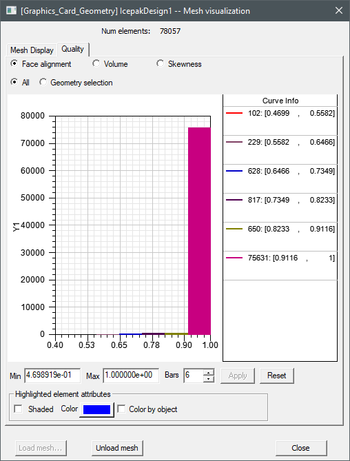
Fig. 1 Face alignment Histogram