
Defining Anisotropic Thermal Conductivity
If the thermal conductivity is anisotropic, either the Cartesian or the Cylindrical coordinate systems can be selected to define the characteristics of its anisotropy tensor. For Cartesian-orthotropic materials you must define three diagonals for the conductivity. Each diagonal represents a tensor of your model along a Cartesian coordinate axis. Cylindrical-orthotropic materials are defined by the axial, circumferential and radial values for the conductivity.
These tensors are relative to the coordinate system specified as the object’s Orientation property. By specifying different orientations, several objects can share the same anisotropic material but be oriented differently.
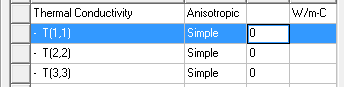
- In the Thermal Conductivity row in the View/Edit Material window, select Anisotropic.
For Cartesian:
- Three rows named T(1,1),
T(2,2), and T(3,3)
are added below the Thermal Conductivity
row.
- Enter the material’s conductivity along each tensor axis in the Value box of the T(1,1), T(2,2) and T(3,3) rows.
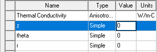
For Cylindrical:
- Three rows named z,
theta, and r are added below the Thermal Conductivity
row.
- Enter the material’s conductivity along each direction in the Value box of the z (axial), theta (circumferential), and r (radial) row.
Geometry Axis and Point of Origin
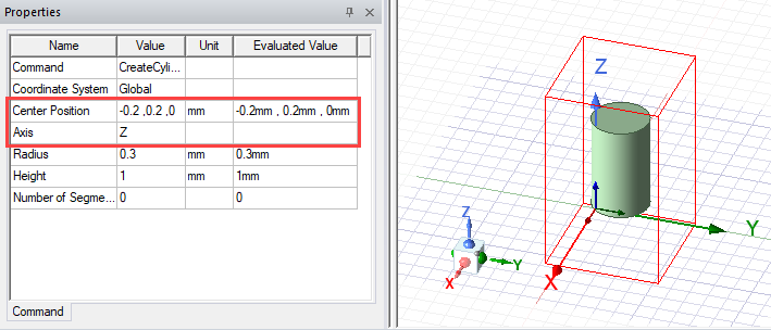
When applying cylindrical orthotropic thermal conductivity, Electronics Desktop determines the axis and point of origin differently based on the selected geometry.
- Cylinder, frustum, sphere, and polyhedron geometry have an Axis defined in the Properties window. The point of origin for the cylindrical orthortropic thermal conductivity is the Center Position displayed in the Properties window.
Note: For inclined geometry, define a relative coordinate system to ensure that the coordinate axis and geometry axis are aligned.
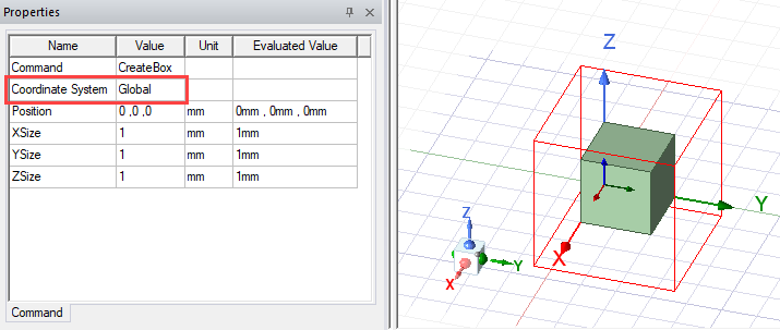
- Box and CAD geometry axis information is determined by the assigned Coordinate System, which is displayed in the Properties window. The point of origin for the cylindrical orthotropic thermal conductivity is the centroid of the geometry.
Limitations for Applying Cylindrical Thermal Conductivity
- Assignment to the native geometry shapes torus, helix, spiral, and bondwire is not supported.
- Assignment to parts of a PCB native component is not supported.
- Assignment to fluid materials is not supported.
- Assignment to geometries with arbitrary rotations relative to the global coordinate system. For example, a cylinder created in a rotated coordinate system consisting of non-orthogonal rotations, such as 45° along X axis, 45° along Y axis, and 45° along Z axis, is not supported.