
Radiation
Overview
The terms radiative heat transfer and thermal radiation are commonly used to describe heat transfer caused by electromagnetic (EM) waves. All materials continually emit and absorb EM waves, or photons. The strength and wavelength of emission depends on the temperature of the emitting material. At absolute zero K, no radiation is emitted from a surface. For heat transfer applications, wavelengths in the infrared spectrum are generally of greatest importance and are, therefore, the only ones considered in Icepak.
While both conduction and convection (the other basic modes of heat transfer) require a medium for transmission, radiation does not. Therefore, thermal radiation can traverse a long distance without interacting with a medium. Also, for most applications, conductive and convective heat transfer rates are linearly proportional to temperature differences. Radiative heat transfer rates, on the other hand, are (for the most part) proportional to differences in temperature raised to the fourth power.
In electronics applications, where the medium of interest is typically air, any absorption (and hence re-emission) and scattering of radiation can be ignored. For such applications, therefore, only surface-to-surface radiation need be considered for analysis.
Gray-Diffuse Radiation
Icepak’s radiation models assume the surfaces to be gray and diffuse. Emissivity and absorptivity of a gray surface are independent of the wavelength. Also, by Kirchhoff’s law , the emissivity equals the absorptivity ( ). For a diffuse surface, the reflectivity is independent of the outgoing (or incoming) directions.
As stated earlier, for applications of interest, the exchange of radiative energy between surfaces is virtually unaffected by the medium that separates them. Thus, according to the gray-body model, if a certain amount of radiation ( ) is incident on a surface, a fraction (
 ) is reflected, a fraction (
 ) is absorbed, and a fraction (
 ) is transmitted. Because for most applications the surfaces in question are opaque to thermal radiation (in the infrared spectrum), the surfaces can be considered opaque. The transmissivity, therefore, can be neglected. It follows, from conservation of energy, that
  = 1, since
  (emissivity), and
  .
.
The Discrete Ordinates (DO) Radiation Model
The discrete ordinates (DO) radiation model solves the radiative transfer equation (RTE) for a finite number of discrete solid angles, each associated with a vector direction  fixed in the global Cartesian system (x, y, z). The DO model solves for as many transport equations as there are directions
  . The solution method is identical to that used for the fluid flow and energy equations.
The DO Model Equations
The DO model considers the radiative transfer equation (RTE) in the direction  as a field equation. Thus, Equation 8 is written as
Equation 8

Angular Discretization and Pixelation
Each octant of the angular space 4 at any spatial location is discretized into  ×
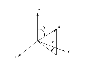
× solid angles of extent, called control angles. The angles are the polar and azimuthal angles respectively, and are measured with respect to the global Cartesian system (x,y, z) as shown in The Angular Coordinate system, shown below. The theta and phi extents of the control angle, are constant. In two-dimensional calculations, only four octants are solved due to symmetry, making a total of directions in all. In three-dimensional calculations, a total of directions are solved. In the case of the non-gray model equations are solved for each band.
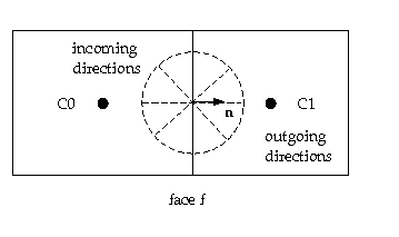
When Cartesian meshes are used, it is possible to align the global angular discretization with the control volume face, as shown in the image below.
For generalized unstructured meshes however, control volume faces do not in general align with the global angular discretization, as shown in the image below leading to the problem of control angle overhang.
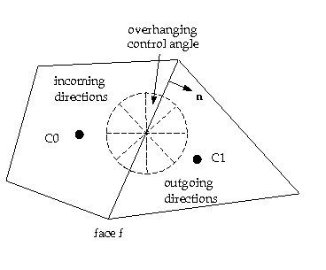
Essentially, control angles can straddle the control volume faces, so that they are partially outgoing to the face. The image below shows a 3D example of a face with control angle overhang.
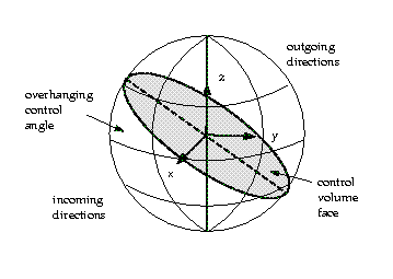
The control volume face cuts the sphere representing the angular space at an arbitrary angle. The line of intersection is a great circle. Control angle overhang may also occur as a result of reflection and refraction. It is important in these cases to correctly account for the overhanging fraction. This is done through the use of pixelation.
Each overhanging control angle is divided into  pixels, as shown in the image below.
![]()
The energy contained in each pixel is then treated as incoming or outgoing to the face. The influence of overhang can thus be accounted for within the pixel resolution. Icepak allows you to choose the pixel resolution. For problems involving gray-diffuse radiation, the default pixelation of 1 X 1 is usually sufficient. For problems involving symmetry, periodic, specular, or semi-transparent boundaries, a pixelation of 3 X 3 is recommended. You should be aware, however that increasing the pixelation adds to the cost of computation.
The Ray Tracing Radiation Model
The ray paths are calculated and stored prior to the fluid flow calculation. At each radiating face, rays are fired at discrete values of the polar and azimuthal angles. To cover the radiating hemisphere,  is varied from 0 to
  and
and  from 0 to
  . Each ray is then traced to determine the control volumes it intercepts as well as its length within each control volume. This information is then stored in the radiation file (.s2s.gz), which is then read in before the fluid flow calculations begin.