
Drawing a Bondwire in HFSS 3D Layout
A bondwire is a thin metal wire that connects a metal signal trace with a chip.
- From the menu bar, click Draw > Primitive >
 Bondwire or, on the Draw ribbon tab, click the Draw bondwire icon:

- Select the bond pad point in one of the following ways:
- Click the point.
- Type the point's coordinates in the text boxes in the status bar.
- Select the lead point by clicking the point or typing the coordinates in the text boxes in the status bar. The Bondwires dialog box opens.
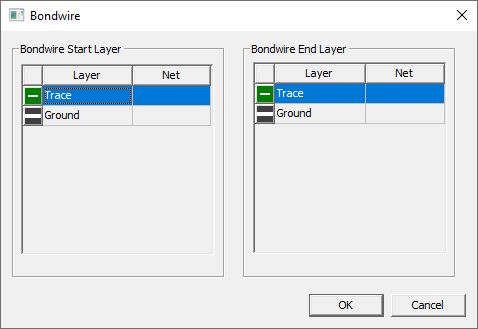
- Select which layers you want the bondwire to start and stop on.
- Click OK. The bondwire appears in the Layout editor.
- To select a new profile definition, click in the Type row of the Properties window and select a modeling standard shape. The choices are APDBondwire, JEDEC4Bondwire, and JEDEDC5Bondwire.
- To change the underlying profile definition, click in the Profile row of the Properties window and click Edit. The Bondwires tab of the Edit Libraries window opens where you can add, edit, import, export, and delete bondwire profile definitions.