
Peak Versus RMS Phasors
This section concerns how field quantities are represented within HFSS. Some users will not need this information, such as those who wish to know port S-parameters or relative amplitudes of field solutions. Those that wish to find absolute field values, for example, will need to review the difference between the two types of field representation, peak and RMS.
HFSS solves in the frequency domain and obtains a phasor representation of the steady-state finite element field solution. Physical quantities such as the instantaneous (time domain) electric field are then obtained as derived quantities from the phasor representation.
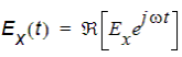
If Ex is the x-component of a "peak" phasor quantity representing a time-harmonic electric field, the physical electric field x-component at time t, denoted Ex(t), is computed from
|
|
|
(1) |
where
- Â is the real part of a complex number or function.
- w is angular frequency, 2pf.
- j is the imaginary unit,
 .
.
- t is the time.
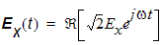
On the other hand, if Ex
is an "RMS" phasor, an additional factor of  is required as
follows:
|
|
|
(2) |
As a consequence of these equations, the peak physical
field, max (Ex(t)) observed
over a full time cycle is max(Ex(t))
= |Ex| for peak
phasors and max(Ex(t))
=  |Ex| for RMS phasors.
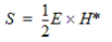
Additionally, given field phasors E and H, to compute the time-averaged power flow through a surface, the normal component of the real part of the complex Poynting vector is integrated over the surface. The correct form of the complex Poynting vector S depends on which phasor representation is used.
 .
.For RMS phasors, E= ExH*.
The conventions used by HFSS are as follows:
- Each propagating mode incident on a port contains 1 watt of time-averaged power.
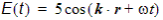
- Circuit gap sources are specified in a peak sense. That is, if a voltage gap source magnitude is 5 volts, then the time domain circuit source behaves as v(t) = 5coswt. Likewise for a current gap source.
- Plane wave sources are specified in a peak sense.
That is, if the plane wave magnitude is 5 V/m, then the plane wave incident
field magnitude is
 .
.
- Radiated power, as computed by the fields post processor, is a time-averaged quantity computed using the complex Poynting vector.
- Phasors in the Fields Calculator are peak phasors.
The Poynting vector button in the calculator
therefore implements the Poynting vector for peak phasors,
Calculations that compute either average or instantaneous time domain quantities must adhere to the peak phasor conventions.