
This topic describes the following SeparationTo commands:
- SeparationToErrors
- SeparationToPolygons
Input: One or two DV layers (containing polygons)
Constraint (operator and distance)
Measurement region qualifier (optional)
Qualifiers (optional)
Intersecting Edge qualifier (optional)
Raw/Merged qualifier (optional)
Output: DV layer – Type varies with the command. SeparationToErrors outputs a DV layer containing error clusters. SeparationToPolygons outputs a DV layer containing polygons.
Description: Separation is the distance between the outside facing edges of separate geometry. The single layer version checks the separation between different geometries on the same layer. The two layer version checks the separation between geometry on one layer and geometry on the other layer. This is an edge-to-edge check, not corner-to-corner, or corner-to-edge.
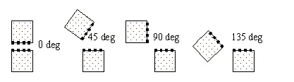
For separation checking, edges are considered to face each other only if the angle between the outsides of the edges is less than 180 degrees. Collinear edges are not considered facing. The following figure illustrates the various angles between outside edges:
The arrows in the figures in the following sections indicate the edge pairs that are checked when considering the facing requirement and using default orientation and intersecting qualifiers: Acute Also, Not Obtuse, Parallel Also, Not Perpendicular, and Not Intersecting.
Single Layer Separation
For a sufficiently large distance, the separation of edges from polygon A to polygon C is measured. The presence of polygon B between them does not prevent the check.

Two Layer Separation
Checking is based on the separation of edges, not the separation of the polygons. In some cases shapes that interact are checked.

- The separation between some edges of polygons F and E is checked even though polygon F overlaps polygon E. Notice the overlap is not checked by this command.
- Abutting edges are not checked by default. To trigger checking of the abutting edges of D and E, use the qualifier Intersecting Also or Intersecting Only.
- Polygon I is not checked against polygon H because the outsides of the edges don’t face. Polygon I is checked against polygon G.
- SeparationToError results are clusters of segments that meet the specified constraint. Each error segment indicates the part of the geometry edge that meets the constraint. The error clusters are returned in a DV layer.
The heavy lines in the following example show the portions of edges that are returned as one error cluster.

SeparationToPolygons results are any polygons that have at least one edge that meets the specified constraints. The polygons are returned in a DV layer. Both polygons in the following example are returned.

The heavy lines in the following example show the segments that are returned as edges. They are not clustered, and they retain information about the directions inside and outside of the polygon and sibling relationship.

The constraint amount may be given with or without units. If no units are specified, the current default length units are used.
Supported operators:
Qualifiers may be specified to constrain the edges checked. The defaults, if no qualifiers are specified, are Round, Acute Also, Not Obtuse, Parallel Also, Not Perpendicular, Not Intersecting, and Merged.
Example (JScript):
var layer1 = DVChecker.ImportLayer("trace");
var sepLayer1 = DVChecker.SeparationToErrors(Array(“<”, “5mm”), layer1,
Array( “Round”, “Acute Also”, “Not Obtuse”, “Parallel Also”,
“Not Perpendicular”));
DVChecker.SaveLayer(sepLayer1, “separation errors”, “sep < 5 on trace layer”);
var layer2 = DVChecker.ImportLayer("ground");
var sepLayer2 = DVChecker.SeparationToErrors(Array(“<”, 5), layer1, layer2,
Array( “Round”, “Acute Also”, “Not Obtuse”, “Parallel Also”));
DVChecker.SaveLayer(sepLayer2, “separation errors”, “sep < 5 trace to ground
layers”);
Measurement Region Qualifier
Measurement region qualifier specifies the construction of the region used to test the constraint. There exist the following choices:
- Round: Forms a region with quarter-circle
boundaries that extend past the corners of the edge by the constraint
distance. Round is the default region, if no region is specified.

- Square: Forms a region with right-angle
boundaries that extend past the corners of the edge by the constraint
distance.

- Opposite: Forms a region with right-angle
boundaries that do not extend past the corners of the edge.

Measurement Region Use To Check Constraint
The following figure displays the returned segment for error or edge output, marked in blue, and the measurement regions, marked in red and green, that are used to check the constraint.

Orientation Qualifiers
Orientation qualifiers specify edge or angle orientations that qualify edges to be checked against each other. Up to one choice from each of the following four groups may be used:
- Acute Also
- Obtuse Also
- Not Parallel
- Not Acute
If multiple choices from any of the groups are used, the last choice on the group is used. It replaces any earlier choices of that group in the command.
SeparationToErrors(Array(“<”, 5), layer, Array(“Acute Also, Obtuse Also, Not Parallel, Not Acute));
is interpreted as:
SeparationToErrors(Array(“<”, 5), layer, Array(“Obtuse Also, Not Parallel, Not Acute));
If a choice contains “Only”, that is the only orientation qualifier recognized. Any other orientation qualifiers before or after the first “Only” is ignored.
SeparationToErrors(Array(“<”, “5mm”), layer, Array(“Acute Also, Obtuse Only, Not Parallel, Perpendicular Only));
is interpreted as:
SeparationToErrors(Array(“<”, “5mm”), layer, Array(“Obtuse Only));
Acute filter
- Acute Also – Include the measurement of edges that have an angle between them greater than 0 and less than 90 degrees. Default if none specified.
- Acute Only – Measure only edges that have an angle between them greater than 0 and less than 90 degrees.
- Not Acute – Do not measure edges that have an angle between them of greater than 0 and less than 90 degrees.
Obtuse filter
- Obtuse Also – Include the measurement of edges that have an angle between them of greater than 90 and less than 180 degrees.
- Obtuse Only – Measure only edges that have an angle between them of greater than 90 and less than 180 degrees.
- Not Obtuse – Do not measure edges that have an angle between them of greater than 90 and less than 180 degrees. Default if none specified.
Parallel filter
- Parallel Also – Include the measurement of parallel edges and non-parallel edges. Default if none specified.
- Parallel Only – Measure only parallel edges.
- Not Parallel – Do not measure parallel edges.
Perpendicular filter
- Perpendicular Also – Include the measurement of perpendicular edges and edges of other orientations.
- Perpendicular Only – Measure only perpendicular edges.
- Not Perpendicular – Do not measure perpendicular edges. Default if none specified.
Intersecting Edge Qualifier
Intersecting Edge qualifier determines if two edges that intersect are checked against each other. Intersecting edges are edges that share at least one point. This qualifier is used in conjunction with the orientation qualifiers to determine which edges to check. One of the three choices may be specified.
- Intersecting Also – Check applies to both intersecting and other edges.
- Intersecting Only – Check only applies to intersecting edges.
- Not Intersecting – Check does not apply to intersecting edges. Default if none specified.
The arrows in the following figure indicate the edge pairs checked using Intersecting Only with the other qualifiers defaulted (Acute Also, Not Obtuse, Parallel Also, Not Perpendicular).

Raw/Merged Qualifier
The Raw/Merged qualifier applies to a DV layer created using the ImportLayer command. Raw specifies the geometry is to be used without first being merged. In contrast, the default setting of Merged specifies the geometry is merged prior to its use.
The arrows in the following figures indicate the edge pairs checked using Raw versus Merged with the other qualifiers defaulted (Acute Also, Not Obtuse, Parallel Also, Not Perpendicular, Not Intersecting).
