
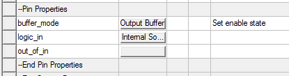
The buffer_mode property sets the connection and condition for the Enable pin on the component (valid only for Input/Output and Tristate buffers). Click the buffer_mode property Value field button to open a window.
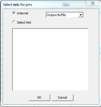
Select Internal to specify internal connections for the Enable pin. When Internal is checked, select buffer mode. The internal options depend on the buffer_type basic property:
- For Input_Outputbuffer_types, select Output Buffer or Input Buffer (default Output Buffer).
- For Tristatebuffer_types, select Output Buffer or High Impedance Buffer (default Output Buffer).
Alternatively, click Select Net. The window displays a list of nets in the circuit to connect to the Enable pin. The text at the upper-right of the window shows the setting of the Enable specification (Active-High, Active-Low) as read on the IBIS model in the file.
Click OK to close the window.
The logic_in Pin property sets the connection for the incoming data source. Click the logic_in Value field button to open a window. Select Internal Source to set up an internal data source (Refer to Eye Source Parameters.) Click Select Net to display a list of nets to connect to the logic_in pin.
For Input_Output buffers, the out_of_in Pin property sets the connection for the (pseudo-digital) output pin that responds to inputs. Click the out_of_in Value field button to open a window. Select on the list of nets to connect to the out_of_in pin.