
Add LNA Solution Setup
A Nexxim Linear network analysis combines the separate analyses in an ECAD-MCAD cosimulation. Each component in the assembly is solved independently using its designated field solver (HFSS, Q3D, or SIwave) and the LNA then ties all the separate subcircuit models together to compute the end-to-end response of the assembled system. Time Domain Reflectometer (TDR) plots are available for LNA and imported solutions in HFSS 3D Layout.
Nexxim Linear network analysis performs a frequency-domain analysis of the circuit that is linearized around the DC operating point. In addition to the basic linear analysis, you can also run a DC noise analysis or run a group delay analysis.
Linear analysis can be used with all passive circuits and with active circuits that operate under small-signal conditions. In linear analysis the signal level and termination values do not cancel the small-signal conditions, so the superposition principle holds.
After a successful linear-circuit analysis, the results reflect the electrical characteristics of the circuit under small-signal conditions. The results of the analysis are linear network parameters such as scattering (S), admittance (Y), hybrid (H), and impedance (Z), gain parameters, stability parameters, and noise parameters. For details, see Linear Network Analysis in the Circuit help topics.
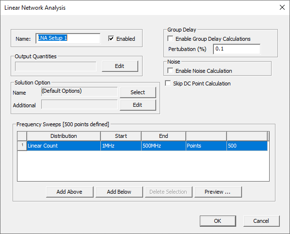
To add a Nexxim Linear Network Analysis to an HFSS 3D Layout project, right-click Analysis in the Project Manager window and select Add LNA Setup to open the LNA Solution Setup window.
You can add solution options by clicking on “Select” in the "Solution Option” area.. For more information, see Transient Analysis Setup.
The LNA setup is passed to the Nexxim solver via a netlist. To view the Nexxim netlist in the Netlist editor, right-click the LNA setup and select Browse Netlist on the menu. For details, see LNA Netlist Syntax in the Circuit help topics.
The Linear Network Analysis runs in co-simulation with a fieldsolver setup in the HFSS 3D Layout project. To select the HFSS Setup for the co-simulation:
- Click HFSS 3D Layout > Solution Setup > Co-Simulation Options to open the Co-Simulation Options window.
- From the Solution selection override area:
- Check the Setup override area. Select a solution setup on the list on the drop-down in the Setup override field.
- Check the Sweep override area. Select a sweep on the list on the drop- down in the Sweep override field.
-
Select Renormalize to re-normalize the Scattering parameter Data (S-data) received on the 3D Layout design before passing it to the Nexxim Circuit solver. Enter the reference impedance value in the ohms box or keep the default of 50 Ohms. If Renormalize is not selected, re-normalization does not take place and the original S-data is passed to the Nexxim Circuit solver.
- Click OK to close the Co-Simulation Options window.
Run the Linear Network Analysis
Right-click the LNA Setup and select Analyze from the menu.
Viewing the Results of the LNA
After the co-simulation has run to completion, you can plot the results of the Linear Network Analysis.
- Right-click the Reports icon and select Create Standard Report>Rectangular Plot on the menu.
- Select your LNA setup as the Solution. The Domain is set to Sweep. The Categories area lists the outputs available on the Linear Network Analysis. Click on a category to view the available Quantities. Valid categories are:
- S-parameters
- Y-parameters
- Z-parameters
- ABCD parameters
- H-parameters
- G-parameters
- Gain parameters
- Stability parameters
- Others
For details, see LNA Results in the Circuit help.
- Click New Report to plot the selected quantities.
-
After LNA has completed, view the solution in the Network Data Explorer. Right-click the LNA setup and select Network Data Explorer on the menu. For details, see Network Data Explorer.