
Digital input nodes for drivers (output, I/O, etc.) use fixed thresholds of 0.2V and 0.8V to trigger changes in state from high to low and low to high, respectively. (See following figure).
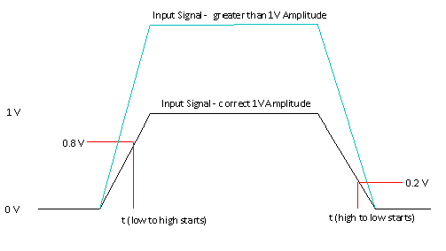
An external voltage supply may be connected to these nodes, but must supply the expected values: 0V for low or off and 1V for high or on. Because the transition trigger thresholds are fixed, duty cycle distortion (DCD) occurs if a high amplitude other than 1Vis used (blue trace in diagram). The amount of DCD is negligible if the transitions themselves are very fast relative to the overall pulse width. Using a high amplitude of less than 0.8V results in no output transitions occurring.
For initial transient values, and for DC analysis, a single fixed input threshold of 0.5V is used. If the input signal is above 0.5V, the output is placed in the high state. Otherwise, the output is placed in the low state.
These descriptions of the relationships between input voltage and output state for the Input buffer nodes assume the Polarity parameter in the IBIS model is set to Non-Inverting. The relationships are appropriately inverted if the IBIS buffer model has Polarity defined as Inverting.