Estimating Matches Between Impedances
Use the Impedance Match menu to estimate matches between an input impedance and a load impedance. The following commands are available:
The Quarter-Wave transformer and the Tuning Stub commands offer two different ways of matching an input impedance to a load impedance. While quarter-wave transformers are more commonly used, tuning stubs may occupy less physical space. Tuning stubs can also be used to match a real input impedance to a complex load impedance, whereas quarter-wave transformers are used only with real input and load impedances.
The Impedance Match commands are only available for trace layers.
Estimating Quarter-Wave Transformer Dimensions
Click the Impedance Match > Quarter-Wave command to estimate the dimensions of a quarter-wave section to match a load impedance to an input impedance.
Before using this command, keep the following in mind:
- The numbers computed by this command are for the selected layer and are rough estimates only. Depending on the substrate parameters, the dimensions of the quarter-wave transformer most likely are different for metals on different layers; therefore, it is important that you select the chosen signal layer first.
- The values estimated by this command may not agree exactly with the values computed by the simulation engine. This command is meant to help you obtain a first iteration design. If you are designing a quarter-wave transformer, you can use the rough dimensions provided as a starting point. Once you have these, you can draw and simulate the structure, then fine-tune the design.
To estimate a quarter-wave transformer:
- Select the trace layer on which the quarter-wave transformer lies.
- Click Impedance Match > Quarter-Wave. Estimate parameters appear in the right side of the Estimate window.
- Type the chosen load impedance in the Load Impedance area, in ohms. The number you enter must be real and greater than 0.
- Type the input impedance in the Input Impedance area. The number you enter must be real and greater than 0. The unit for impedance is ohms.
- Type the frequency in the Frequency area, in GHz. This frequency is independent of the maximum frequency entered in the solution setup.
- Click Calculate
to perform the estimate. The estimated information appears in the following
boxes:
Impedance
Displays the impedance required to match the input impedance to the load impedance. The unit for impedance is ohms.
Width
Displays the line width of the quarter-wave section in the current working units.
Length
Displays the line length of the quarter-wave section in the current working units.
Estimating Tuning Stub Parameters
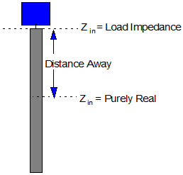
Click the Impedance Match > Tuning Stub command to obtain an estimate of the location and the dimension of a tuning stub for matching an input impedance to a complex load impedance. The tuning stub is assumed to be an open-ended stub. If you have a microstrip line terminated in a complex load impedance, you can also use this command to estimate the location along the microstrip line where the input impedance, looking toward the load, is purely resistive.
Before using this command, keep the following things in mind:
- The numbers computed by this command are rough estimates only. Depending on the substrate parameters, the patch parameters may be different for patches on different layers; therefore, it is important that you select the chosen signal layer before accessing this command.
- The estimated values may not agree exactly with the values computed by the simulation program. This command is meant to help you obtain a first iteration design. If you are designing a tuning stub, you can use the rough dimensions provided as a starting point. Once you have these, you can draw and simulate the structure, then fine-tune the design.
To estimate the location and the dimensions of a tuning stub:
- Select the trace layer on which the tuning stub lies.
- Click Impedance Match > Tuning Stub. Estimate parameters appear on the right side of the Estimate window.
- Type the frequency in the Frequency area, in GHz. This frequency is independent of the maximum frequency entered in the solution setup.
- Type the line width of the microstrip line connected to the load impedance in the Line Width area. The units for the width are the same as the current working units. The width of the tuning stub is assumed to be the same as the width of the line connected to the load.
- Type the real part of the complex load impedance in the Real area. The number you enter must be real and greater than 0. The units for impedance are ohms.
- Type the imaginary part of the complex load impedance in the Imaginary box.
- Click Calculate
to perform the estimate. The estimated information appears in the following
boxes:
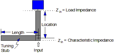
Location, D
Displays the estimated location for the tuning stub in the current working units. This is the distance measured on the load impedance along the microstrip line.
Length, L
Displays the estimated line length for the open-ended stub in the current working units. The width of the stub is assumed to be the same as width of the microstrip line specified in the input area.
Distance Away
Displays the location along the microstrip line where the input impedance, looking toward the load, is purely real. The estimated location is the distance measured on the load along the microstrip line. The unit for the distance is the same as the current working units.
Real Impedance
Displays the impedance value at the location along the microstrip line where the input impedance, looking toward the load, is purely real.
The following figure displays the location and line length for an open-ended stub. The width of the stub is assumed to be the same as the width of the microstrip line specified in the input area:
The following figure displays the location along a microstrip line where the input impedance is purely real: