
Estimating Dimensions of Printed Antennas
Use the Printed Antennas menu to estimate the dimensions of two different types of singly fed, circularly polarized (CP) patches and the resonating length of a rectangular patch. This command is not available for infinite negative signal layers or trace layers between two infinite negative signal layers.
The following commands are available:
|
Estimates the dimensions of a corners-truncated CP element. |
|
|
Estimates the dimensions of a nearly square CP element. |
|
|
Estimates the resonating length of a rectangular patch. This command also estimates the bandwidth and the radiation efficiency of the patch and the location on the patch corresponding to an impedance value. |
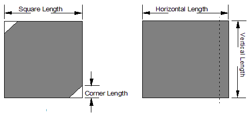
Click the CP Corners Truncated and CP Nearly Square commands to obtain estimates on the dimensions of two different types of singly fed CP patches. To generate circular polarization on a patch using a single feed, you must excite two orthogonal modes on the patch. To obtain two orthogonal modes on a patch, you generally start with a square patch and perturb the element. You can perturb the element by cutting away two opposite corners of the patch or by extending one of the sides slightly. The following figure demonstrates the two types of singly fed CP patches:
Estimating Corners-Truncated CP Element Parameters
Use this command to estimate the dimensions of a corners-truncated, circularly polarized (CP) element. The feed points for these patches are not arbitrary. For a corners-truncated patch, you need to feed the patch along the center line of the patch in order to excite the two orthogonal modes.
Before using this command, keep the following in mind:
- The values estimated by this command are for the current active layer only. Depending on the substrate parameters, the patch parameters may be different for patches on different layers; therefore, it is important that you select the chosen signal layer before accessing this command.
- This command is unavailable if your structure does not contain negative signal planes or if it contains two negative signal planes and you have selected a signal layer between them.
- The method used to estimate the patch parameters is an approximate method based on the cavity model; therefore, the values given are only rough estimates.
To estimate a CP corners-truncated patch:
- Select the trace layer on which the patch lies.
- Click Printed Antennas > CP Corners Truncated. Estimate parameters appear on the right side of the Estimate module’s window.
- Enter the frequency in the Frequency area, in GHz. This frequency is independent of the maximum frequency entered in the solution setup.
- Click Calculate
to perform the estimate. The estimated information appears in the following
boxes:
Square Length
Displays the estimated dimension of the unperturbed square patch in the current working units.
Corner Length
Displays the estimated dimension of the corner to be cut away on the unperturbed square patch in the current working units. The shape of the cut-away corner is a right angle triangle having two equal sides along the edges of the patch.
Estimating Nearly Square CP Element Parameters
Use this command to estimate the dimensions of a nearly square, circularly polarized (CP) element. The feed points for these patches are not arbitrary. For a nearly square patch, you need to feed the patch at the corner of the patch.
Before using this command, keep the following things in mind:
- The values estimated by this command are for the current active layer only. Depending on the substrate parameters, the patch parameters may be different for patches on different layers; therefore, it is important that you are on the chosen signal layer before accessing this command.
- This command is unavailable if your structure does not contain negative signal planes or if it contains two negative signal planes and you have selected a signal layer between them.
- The method used to estimate the patch parameters is an approximate method based on the cavity model; therefore, the values given are only rough estimates.
To estimate a CP nearly square patch:
- Select the trace layer on which the patch lies.
- Click Printed Antennas > CP Nearly Square. Estimate parameters appear on the right side of the Estimate module’s window.
- Enter the frequency in the Frequency area, in GHz. This frequency is independent of the maximum frequency entered in the solution setup.
- Click Calculate
to perform the estimate. The estimated information appears in the following
boxes:
Horizontal Length
Displays the dimension of the perturbed patch in the horizontal or x direction in the current working units.
Vertical Length
Displays the dimension of the perturbed patch in the vertical or y direction in the current working units.
Estimating Rectangular Patch Parameters
Use this command to obtain a rough estimate of the resonating length of a rectangular patch. This command also estimates the bandwidth and the radiation efficiency of the patch and the location on the patch that corresponds to a user-specified impedance value.
Before using this command, keep the following in mind:
- The method used is an approximate method based on the cavity model. The numbers estimated by this command are only rough estimates. Depending on the layer parameters, the patch parameters may be different for patches on different layers; therefore, it is important that you select the chosen trace layer before using this command.
- The estimated values may not agree exactly with the values computed by the simulation engine. The purpose of this command is to help you obtain a first iteration design. If you are designing a patch, you can use the rough dimensions as a starting point. With these, you can draw and simulate the structure, then fine-tune the design.
- This command is unavailable if your structure does not contain negative signal planes or if it contains two negative signal planes and you have selected a signal layer between them.
To estimate a rectangular patch:
- Select the trace layer on which the patch lies.
- Click Printed Antennas > Rectangular Patch. Estimate parameters appear on the right side of the Estimate module’s window.
- Select Square Patch to enable the square patch option. For square patches, you do not need to specify the non-resonating length of the patch, which is entered in the Vertical Length, W area.
- Enter the frequency in the Frequency area, in GHz. This frequency is independent of the maximum frequency entered in the solution setup.
- Enter the dimension for the non-resonating edge of the rectangular patch in the Vertical Length, W area. The number must be greater than 0. The units are the same as the current working units.
For a rectangular patch, the resonating edge of the patch is along the horizontal, or x, direction and the non-resonating edge is along the vertical, or y, direction. This box is unavailable if the Square Patch option is selected.
- Enter the chosen voltage standing wave ratio (VSWR) in the VVSWR area. The number entered must be greater than or equal to 1. This value is used to estimate the bandwidth of the patch.
- Enter the chosen input impedance in the Input Impedance area, in ohms. The number you specify must be greater than 0. This option is useful for finding an optimal location for feeding or loading the patch. When the estimate is calculated, HFSS estimates a location on the patch where the input impedance is close to the value you specified.
- Click Calculate
to perform the estimate. The estimated information appears in the following
boxes:
Horizontal Length, L
Displays the estimated length for the resonating edge of the patch antenna. The units are the same as the current working units.
Bandwidth(%)
Displays the estimated bandwidth (in percent) at the VSWR setting you specified for the patch antenna.
Radiation Efficiency (%)
Displays the estimated radiation efficiency (in percent) for the patch antenna.
Impedance Location
Displays the approximate location on the patch where the input impedance is close to the impedance you specified. This location is specified by a horizontal offset and a vertical offset. The Horizontal Offset and Vertical Offset group boxes display these offset values. The horizontal offset value is the distance along the x direction relative to the lower-left node of the patch. The vertical offset value is the distance in the y direction relative to the lower-left node of the patch. The unit for these boxes is the same as the current working unit.