
N-port frequency-dependent data such as S-parameters can be entered manually instead of reading it from a file. To create an N-port element to receive manually entered data, select the Circuit project that contains it.
- View the Component Libraries area, select the Symbols tab. Click Import Models.
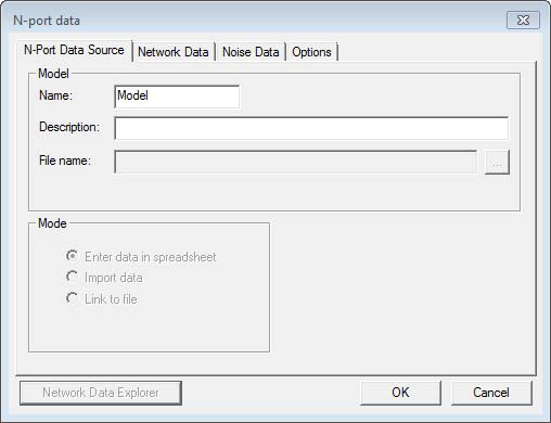
- Select the NPort_NoFile icon to open the N-port data window. The Mode is set to Enter data in spreadsheet.
- Click Network Data tab.
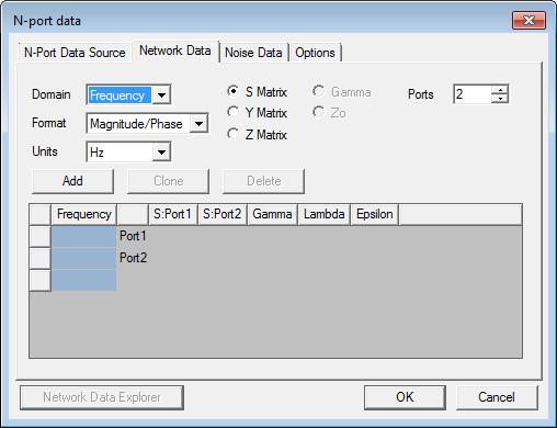
The Network Data tab is used to view the data from an imported file, or to enter the N-port data manually.
- Domain – Selects the Frequency or Time domain.
- Format – Selects the Format to one of the following: Magnitude/Phase, Real/Imaginary, or dB Phase.
- Units – From the Frequency domain, selects the units of frequency: Hz, KHz, MHz, GHz, THz, or rps. From the Time domain, selects the units of time: fs, ps, ns, us, ms, or s.
- S Matrix – Identifies the data as S-parameter values
- Y Matrix – Identifies the data as Y-parameter values
- Z Matrix – Identifies the data as Z-parameter values
- Gamma – Identifies the data as Gamma values
- Z0 – Identifies the data as Z0 values
- Ports – Sets the number of signal ports
- Phase Rotation — Click to set the Phase Rotation of the N-Port Network Data source.The Noise Data and Options tabs are the same as for the file-based N-port. See Editing an N-Port Model.
-
Click OK. An instance of the N-Port is attached to the cursor so drag and drop it in the schematic.