
The first step is to create a schematic symbol to represent the Verilog component. A symbol consists of a graphic design with pins for the electrical nodes that connect the component to the circuit. In this example the Verilog symbol is a copy or “clone” of a Nexxim resistor symbol.
(See Using the Symbol Editor in the Component Libraries topic for additional details on creating a new symbol.)
- Start the Electronics Desktop. Insert a new Circuit design. Select None in the Choose Layout Technology window.
- From the menu, select Tools>Edit
Libraries>Symbols. The Edit Libraries window opens with
the Symbols tab. Ensure both the Show Project definitions
is checked (on) and the Show all libraries boxes are not checked.
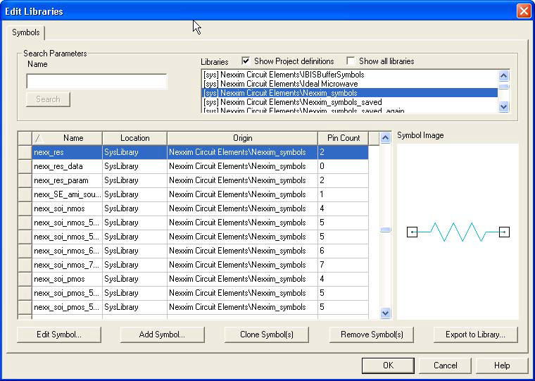
- Scroll to the symbol library file containing
the symbol to be cloned. In our example, the file is Nexxim Circuit
Elements/Nexxim_Symbols. Scroll to the symbol, nexx_res in
our example. Click on that symbol to select it, and click Clone
Symbol to open the Get Name window. Enter
the name for the Verilog symbol, in this example nexx_Verilog_res.

- Click OK to close the Get Name window. The new symbol appears in the Edit Libraries window listing as a Project symbol.
- Click new symbol and click Edit Symbol to open the Symbol Editor window with the resistor symbol displayed.
- Click left terminal so the
properties of the terminal appear in the Properties window.

- Click Value for the
PinName property to open the Global Port Name window. Rename
the terminal to match the node name in the Verilog model. In this example,
the terminal has been renamed to positive.

- Select the other terminal and rename it. In our example the new name is negative.
- From the menu, select Symbol>Update Project. Close the Symbol Editor window.
- From the menu, select Tools>Edit Libraries>Symbols. The Edit Libraries window opens with the Symbols tab. Ensure the Show Project definitions is checked (on) and the Show all libraries boxes are unchecked (off).
- Scroll to the symbol you just created, in our example, nexx_Verilog_res in the Project. Select the symbol and click Export Symbol to open the Export to user library window.
- The Electronics Desktop saves user-defined objects in a PersonalLib directory that is specified at install time. To change the location of the PersonalLib directory, select Tools>Options>General Options.
- Click the Create New Folder icon at the upper-right of the window to create a new folder named Verilog. Click new directory to open it, then save the symbol in a new library file named Verilog_Symbols.aslb. The Electronics Desktop prompts you to verify the creation of the new library file.
Now the symbol has been created, the next step is to create a component.