
The component definition provides all the information needed to instantiate the component in the schematic and generate a correct netlist for Nexxim to simulate. In this example the component is copied (“cloned”) from a standard Nexxim resistor.
See Using the Component Editor in the Component Libraries topic for details on creating a new component.
- From the menu, select Tools>Edit Libraries>Components. The Edit Libraries window opens on the Components tab. Ensure the Show Project definitions is checked (on) and the Show all libraries box is unchecked (off).
- The Libraries area at the upper right lists all the categories of Nexxim components. Scroll to the Nexxim Circuit Elements\Resistors category, and click on that category. The window reopens to show the Nexxim resistor components. Click on the RES_ component to select it, and click Clone Component to open the Edit Component window. Enter the name RES_Verilog.
- From the Edit
Component window, click the Symbol [...] button to open the Select
Definition window. Ensure the Show Project definitions
is checked (on) and the Show all libraries box is unchecked
(off). Select [personal]Verilog/Verilog_Symbols on the libraries
listing. From the Personal Library, select nexx_Verilog_res. Then click OK to close the Select
Definition window.

- Select the Miscellaneous tab on the Edit Component window, and change the Description to Resistor, Verilog.
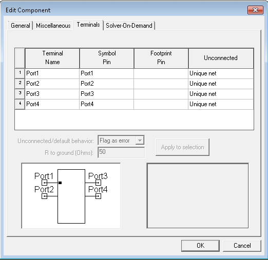
- Select the Terminals tab and verify
the terminal names have been read on the symbol.
- Select the General tab, and click Properties to open the Edit Properties window.
- Select and Remove any properties that should not be used in the Verilog component. In our resistor example, the properties to be deleted are ADDNOISE and DTEMP.
- The component requires a file property to link to the Verilog model. Click Add to open the Add Property window. Enter file as the Name, click FileName for the property type, and enter required as the value. When the component is instantiated in the schematic, users set the file property by selecting the Verilog library file from a Select File window.
- The component requires a unique name.
Click Add again. Enter SubcktName as the Name, click
Text, and enter required as the value.
When the component is instantiated, users set the SubcktName
property to a unique name.
Note:
In general, the name given for the SubcktName property must be the same as the module name specified in the Verilog code, or the compilation process fails. If the SubcktName is specified as “resistor,” as in this example, the simulation runs successfully irrespective of the name of the Verilog-A module defined in the .va file. The statement “resistor” calls the default resistor model available in Spectre.
- Add any additional parameters required as input variables in the Verilog model you are accessing. The resistor model in our example uses only variable R for the resistance. This property is already in the Nexxim resistor component. When the component is instantiated in the schematic, users set these parameters to the chosen values. The instance values are passed to the Verilog model during simulation of the circuit.
- Click CosimDefinition property Edit button (or click Solver-on-Demand tab of the
Edit Component window, then click Edit for
the Default Netlist entry). Edit the netlist string to the following:

The Multi-product Netlist definition specifies the format for the netlist entry that are generated by instances of the Verilog component. In this string:
- simulator lang=spectre turns on the Spectre interpretation of the entries. The equals sign may look like a hyphen.
- [...] entries are newlines.
- @file is the user-supplied name of the Verilog library file.
- R@ID is the reference designator, the letter R followed by a unique number (e.g., R23).
- \( and \) are literal left and right parentheses.
- %0 and %1 are filled in with
the names of the circuit nodes attached to the resistor terminals. If
your component has more than two terminals, add %2, %3,
etc.)
Note:
The spaces around the %0 and %1 separating them on the parentheses are REQUIRED.
- @SubcktName is the user-supplied name of the Verilog subcircuit.
- R=@R netlists the resistance value, the characters R= followed by the value of the R property (@property puts the value of property in the netlist). Any other properties in the model should be added to the netlist string using this format.
- simulator lang=nexxim turns on the Nexxim interpretation of the resulting netlist. The equals sign may look like a hyphen.
- Click OK to close the Multi-product Netlist definition window. Click OK to close the Properties window. Click OK to close the Edit Component window.
- Select the new component in the Edit Libraries window and click Export to Library. Open the Verilog directory under PersonalLib, and save the resistor component in a new library file, Verilog_Resistors.aclb. The Electronics Desktop prompts you to confirm the creation of the new file.
- This completes the process for creating the Verilog component.
- View the Component Libraries window, and click the Symbols tab. Click Proj to display the Project components. The new component appears in the window.
- To create an instance of the component, double-click the RES_Verilog entry, drag the cursor into the design area, and select Place and Finish on the menu.
- Select the resistor and open the Properties
window:

- Set the R, file, and SubcktName properties. Click OK to close the Properties window.
- Here is a listing of file resistor.va:
// Simple resistor
`include "disciplines.vams"
module Verilog_R1(p,n);
input p,n ;
parameter real R=1.0 from (0:inf);
electrical p,n;
real ir ;
analog begin
ir = V(p,n)/R;
I(p,n) <+ ir ;
end
endmodule
- Connect the component and simulate.