
Link to DesignXplorer
You can export a .xml file containing information on
To do so:
- Click your product on the menu bar and
then Optimetrics Analysis > Add Design Xplorer Setup or right-click
on Optimetrics in the Project Manager window, and select Add
Design Xplorer Setup from the short-cut menu.
This opens the Design Xplorer dialog box with the General tab selected. it lists the setups available in the current project, and the input variables it contains.
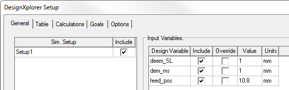
- Select Include for the simulation setups you want to use.
- Check the Design variables to use. You can also chose to Override the value of a design variable. You can edit the Value and Units fields. Unchecking Override returns the values to their original state.
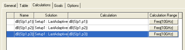
- To set up any output calculations, click the Calculation tab and click Setup Calculations.
This opens the Add/Edit Calculation dialog box. Here you can define the simulation results of interest. The dialog box contains distinct panes and tabs to set the Context, the Calculation Expression, and the Calculation Range. See: Setup Calculations for Optimetrics for details.
Use the Add Calculation button to add expressions to the Calculations table.
- When you have added the calculations of interest, click OK to save the setup.
An icon for the Design Xplorer setup appears under Optimization in the Project tree.

- To create a .xml file with the setup information for Design Xplorer, first Save your project.
- Then right-click the setup and select Export External Connector Addin Configuration.
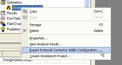
This displays a browser dialog that you can use to navigate your file system and name and saves the .xml file. This file contains information regarding the path along with the setup, variables, and simulation results that you specified.
- If you have an Ansys Workbench installation you can perform additional steps. You should have provided a path to the Workbench installation in the Tools > General Options dialog box Miscellaneous tab, to provide a path.
- Then click Create Workbench Project.
This lets you name a Workbench project containing the information in the setup. The Ansys Workbench will be launched with the connection to the project established. To this connection, you can add a Design Xplorer Setup.