
Splitting Objects
To split an object or several objects using one of the global planes (XY, YZ, or XZ) or a plane based on a selected face or arc, use the Modeler> Boolean> Split command.
- Select the object you want to split. You can select more than one object.
- From the menu bar, click Modeler> Boolean>
 Split or, on the Draw ribbon tab, click the Split icon:
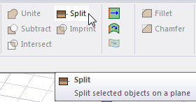
The Split dialog box appears. Also, a cyan colored wheel shows the current split plane and points toward the positive side of the plane.
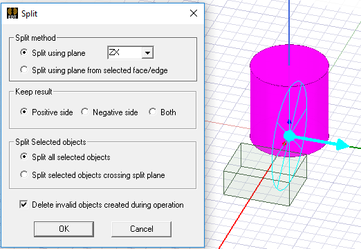
- Choose the desired Split method and specify the splitting plane:
- Split using plane: Select the desired splitting plane (XY, YZ, or XZ) from the drop-down menu, or
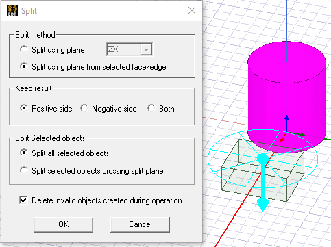
- Split using plane from selected face/edge: Select a single face or edge (specifically, a planar face or arc) to define the splitting plane.
The following example shows the top face of the box being used to define the splitting plane for the cylinder:
- Select one of the following Keep result options to specify which object fragments you want to keep:
- Positive side: Keep objects on the positive side of the splitting plane.
- Negative side: Keep objects on the negative side of the splitting plane.
- Both: Keep objects on both sides of the splitting plane.
The split plane is shown using a cyan colored wheel with spokes, as seen in the images above and below left. A cyan arrow indicates which side of the split plane is the positive side.
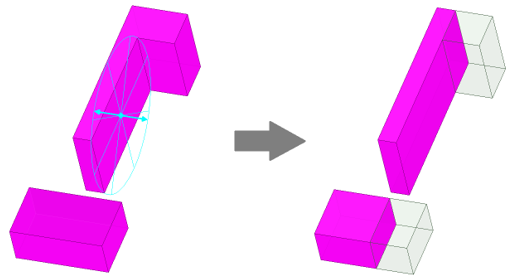
In the following example, the YZ plane (green and blue axes) is the splitting plane, and the result on the positive side was kept. The picture on the left is before the split. The picture on the right is the result of the completed Split command:
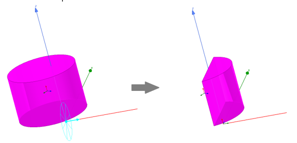
The next example shows the second Split method (Split using plane from selected face/edge). You can only select one entity, a planar face or an arc (selected as an edge). The face or edge used to define the splitting plane need not belong to one of objects selected to be split. You can select any face or arc edge in the model.. You can pan, zoom, or rotate the model viewpoint as needed to make the selection easier. Also, the Keep result for Both sides option was selected. (Notice the arrow is in both directions for the split plane graphics.) The picture on the left is before the split. The picture on the right is the result of the completed Split command:
- Select one of the following Split Selected objects options:
- Split all selected objects: Select this option if you do not want to preserve objects that are not crossing the split plane but are part of the selection.
- Split all selected objects crossing split plane: This option allows you to identify selected objects that do not cross the split plane and ignore them for the operation. For a multiple selection, only those objects that cross the split plane are split; others are kept intact. By design, splits in existing designs from previous software versions are not changed.
- Optionally, select the Delete invalid objects created during operation. If you choose to Split all selected objects, the operation could create invalid objects (if split plane does not cut any of selected objects and any are on the side not being kept). This option deletes any such invalid objects that might be created.
- Once the proper selections have been made, click OK.
The objects are divided and retained as specified.