Lumped Ports
Lumped ports support single mode excitations when S-parameters have to be extracted at internal locations of a model. It can also be used to represent a terminal of a passive component to be subsequently optimized in a circuit simulator using S-matrix description of the model.
For designs with only lumped ports or a combination of lumped and circuit ports, the Advanced Solution Setup, Options tab includes an option to use Enhanced low frequency accuracy. The previous port solution procedure can experience failures at low frequencies. Once enabled, the feature is transparent to the user. There may be slight variations in the number of triangles, but these are not reported for lumped ports. Reported 3D mesh size may be different, and the number of adaptive passes may change.
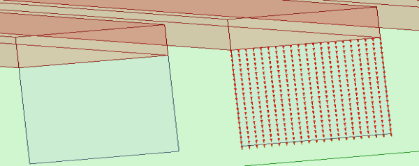
For lumped ports all edges that do not touch metal are
treated as perfect H boundaries. From this definition the resulting field
distribution on the lumped port geometry is solved with the wave port
solver. For a rectangular lumped port this results in electric fields
orientated parallel to these perfect H sides. See figures below. The
physical geometry of the rectangular lumped port carries current with
the corresponding H fields resulting in parasitic inductance. For these
same rectangular lumped ports the parasitic inductance can be calibrated
out of the s-parameter response with the deembedding option for lumped
ports.